



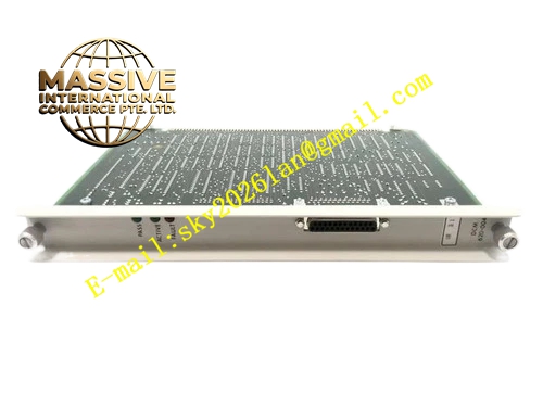
Description
Honeywell 620-0045
Technical Specifications
- Backplane Bus: IPC620 proprietary I/O Link backplane bus
- Network Ports: Two independent shielded RJ45 10BASE-T ports
- Network Rate: 10 Mbps auto negotiation half / full duplex
- Communication Protocol: Modbus TCP
- Redundancy Mode: Hot standby link redundancy, automatic path switching
- Isolation Rating: 1500 VAC isolation between each network port and backplane circuit
- Inter-port Isolation: 500 VAC isolation between two Ethernet channels
- Supply: 5 VDC from rack backplane
- Operating Temperature: 0 °C to +60 °C
- Power Consumption: 6.1 W maximum
- Hot Swap Support: Yes
Functional Features Two completely independent Ethernet physical channels with separate PHY circuits. Configurable hot standby redundancy mode, automatic switch to backup link when primary link fails. Each port supports Modbus TCP server and client mode separately. Independent link, TX and RX LED indicators for port 1 and port 2 on front panel. Link switching logic runs on hardware level, and switching delay is fixed. Each network channel carries independent surge and ESD protection circuit. Network fault diagnosis data of two ports can be uploaded to PLC separately. TCP connection state of each port is recorded in controller diagnostic register.
Application Scenarios Redundant Ethernet SCADA monitoring for IPC620 critical process control rack Dual network topology of chemical plant emergency interlock auxiliary control system Dual HMI redundant access of power plant water treatment IPC620 controller Network communication spare replacement for high-reliability IPC620 redundant control cabinet Data exchange between IPC620 and dual redundant server system
Performance Parameters
- Link switching time: Less than 800 ms
- Maximum concurrent TCP connections for each port: 8 connections
- Isolation withstand voltage: 1500 VAC for 60 seconds
- Maximum cable length per port: 100 m CAT5 twisted pair
- Frame forwarding error rate: Less than 1 × 10⁻¹² under normal link condition
Material Composition Multilayer FR4 PCB, dual Ethernet PHY chips, FPGA redundancy logic and protocol processing chip, dual network isolation transformers, optocoupler isolation array, TVS surge diodes, decoupling capacitors, two shielded RJ45 connectors, gold-plated backplane edge connector, UL94 V0 plastic front panel.
Structural Features Standard eurocard plug-in size for IPC620 rack slot. Two RJ45 connectors are arranged side by side on front panel with independent LED group. Two network channels are separated by isolation barrier on PCB layout to avoid crosstalk. Redundancy mode configuration DIP switch is set behind dust-proof plastic cover. Anti-keying notch prevents mis-insertion into single Ethernet or serial communication slot. Heat dissipation copper area is laid for FPGA and PHY chips to adapt continuous full-load operation.
Working Principle The module receives I/O Link bus data from CPU and copies data stream to two Ethernet channels at the same time under redundancy mode. Primary port transmits Modbus TCP frame to remote host, and backup port keeps link establishment state. When primary port link failure is detected, hardware logic immediately switches data transmission to backup port without CPU intervention. Two network ports receive Ethernet data independently, and valid request frame is transmitted back to CPU through I/O Link bus after verification. Each port monitors link pulse continuously and reports independent fault information.
Installation Requirements Power down the rack before installation and redundancy parameter configuration. Two network ports connect to two independent network switches of redundant network respectively. Set consistent IP segment and Modbus parameter for two ports according to system design. Use shielded CAT5 twisted pair cable for both network channels. Set redundancy enable and primary/backup port definition in IPC configuration software. Simulate network cable disconnection test after commissioning to verify automatic switching function.
Usage Notes Two ports cannot be connected to the same switch port to avoid network loop. Do not set the same IP address for port 1 and port 2 in non-redundancy application. Network lightning surge protection device must be installed at the cabinet inlet of long-distance network cable. Link switching action will cause short data pause of upper host. Do not modify onboard redundancy configuration circuit components.







