



Description
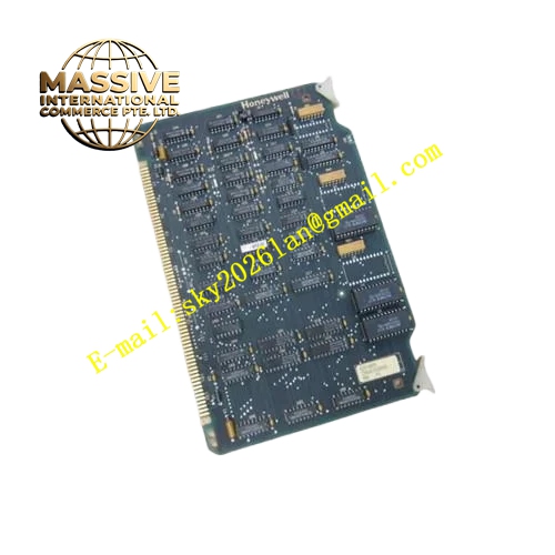
Honeywell 620-0054
Technical Specifications
- Channel Quantity: 4 high speed measurement channels
- Input Signal Type: Single-ended pulse, A/B quadrature differential encoder
- Maximum Input Frequency: 120 kHz per channel
- Input Level: 5 VDC or 24 VDC configurable per channel
- Counter Register: 32-bit signed hardware counter
- Isolation Rating: 250 VDC optical isolation per channel
- Backplane Interface: IPC620 I/O Link backplane bus
- Operating Temperature: 0 °C to +60 °C
- Power Consumption: 5.2 W maximum
- Hot Swap Support: Yes
Functional Features Asynchronous hardware counter runs independently of PLC scan cycle without pulse missing. Quadrature decoding supports 1x, 2x, 4x resolution multiplication for rotary encoder. Configurable hardware latch function captures pulse value at external trigger edge. Accumulated totalizer value can be stored in non-volatile memory during short power failure. Per-channel input signal fault detection for open circuit and abnormal signal amplitude. Front panel LED indicates pulse activity and module communication fault. All count and frequency data frames carry CRC checksum.
Application Scenarios High speed pulse totalization of turbine flow meter for oil and gas metering Rotary encoder position tracking for material positioning equipment Compressor and engine shaft speed measurement through magnetic pickup sensor Batch metering and flow accumulation control in chemical batch process IPC620 high speed pulse acquisition channel spare replacement
Performance Parameters
- Counting accuracy: ±1 pulse within full frequency range
- Hardware latch response time: Less than 1 μs
- Non-volatile data retention time: 10 years minimum
- Isolation withstand: 250 VDC for 60 seconds
- Frequency update interval: Configurable from 10 ms to 1000 ms
Material Composition Multilayer FR4 PCB, FPGA high speed counting logic chip, optocoupler isolators, Schmitt trigger signal shaping chip, TVS surge suppression diodes, decoupling ceramic capacitors, gold-plated backplane edge connector, flame retardant plastic front panel with extraction handle.
Structural Features Standard plug-in eurocard form factor matching IPC620 rack slot. Rear gold edge connector mates with IPC620 backplane I/O Link bus. Internal isolation barrier separates field pulse signal circuit and logic circuit. A/B/Z signal terminals of each encoder channel are grouped together on wiring area. Anti-keying notch prevents reversed insertion into ordinary digital input slot. High speed differential traces for quadrature signals adopt equal length layout.
Working Principle Field pulse or quadrature encoder signal passes through optocoupler isolation and Schmitt trigger shaping circuit to eliminate jitter. FPGA hardware counter accumulates pulse number and executes quadrature decoding algorithm according to configuration. Frequency value is calculated by counting pulse quantity in fixed time window. External trigger signal activates hardware latch to freeze current counter value. Count data, frequency value and diagnostic flags are packed into I/O Link frame and transmitted to IPC620 CPU. Preset count comparison function can generate internal event flag automatically.
Installation Requirements Encoder and pulse instrument wiring adopts shielded twisted pair cable. Set input voltage level, quadrature multiplier and latch trigger edge in IPC software. Separate high speed pulse cable from power cable to reduce induced noise. Verify count value synchronously changes with field rotating equipment during commissioning. Confirm firmware version supports quadrature encoder function.
Usage Notes Do not exceed maximum 120 kHz input frequency of each channel. Poor shield grounding will cause miscount and signal jitter of quadrature encoder. Totalizer reset command can only be issued through authorized control program. Do not modify onboard high speed input shaping circuit components.







