



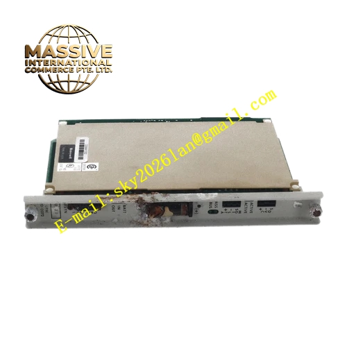
Description
Honeywell 620-0072
Technical Specifications
- Backplane Interface: IPC620 I/O Link proprietary bus
- Input Channels: 4 differential quadrature encoder channels with A/B/Z phase support
- Maximum Input Frequency: 150 kHz per channel
- Input Level: 5 VDC differential, 24 VDC single-ended configurable
- Counter Register Width: 32-bit signed hardware counter
- Isolation: 250 VDC optical isolation for each input channel
- Power Supply: 5 VDC drawn from rack backplane
- Operating Temperature: 0 °C to +60 °C
- Storage Temperature: -40 °C to +85 °C
- Relative Humidity: 5 % to 95 % non-condensing
- Hot Swap Support: Yes
- Power Consumption: 5.3 W maximum
Functional Features Hardware asynchronous counting eliminates pulse loss during fast signal variation. Quadrature decoding supports 1x, 2x and 4x resolution multiplication. Hardware latch function freezes counter value at external trigger edge. Per-channel open-circuit and amplitude fault diagnosis for field wiring. Built-in non-volatile memory retains accumulated totalizer data during short power interruption. Front panel LED array shows channel pulse activity, module communication status and fault alarm. All measured frequency, count and diagnostic data carry CRC checksum for transmission verification. Programmable digital filter suppresses high-frequency electromagnetic noise on input lines.
Application Scenarios Turbine flowmeter pulse accumulation for oil and gas metering skids Rotary encoder position tracking for batch processing machinery Compressor, pump and turbine shaft speed monitoring via magnetic pickup sensors Continuous batching and cumulative flow recording in chemical process lines Spare channel replacement for existing IPC620 pulse measurement racks
Performance Parameters
- Counting accuracy: ±1 pulse across full rated frequency range
- Hardware latch response time: Less than 1 μs
- Non-volatile data retention period: 10 years minimum
- Common mode rejection ratio: 86 dB minimum
- Fault detection response: Less than 200 ms for broken wire events
Material Composition Main circuit substrate: Multilayer FR4 PCB with UL94 V0 flame retardant rating Processing core: High-speed FPGA logic chip for counting and decoding Signal conditioning: Schmitt trigger shaping IC, high-speed optocoupler isolators Protection components: TVS diodes, ferrite noise suppression beads, ceramic decoupling capacitors Connectors: Gold-plated backplane edge connector, screw terminal block for field signals Front panel: Black flame retardant nylon plastic with extraction latch
Structural Features Standard eurocard plug-in form factor compatible with IPC620 rack guide slots. Field signal terminal block and LED indicators are centrally arranged on front panel. Internal isolation barrier separates field pulse signal circuit and backplane logic circuit. Anti-keying mechanical notch prevents mis-insertion into analog or digital I/O slots. Differential signal traces adopt equal-length layout to maintain quadrature phase matching. Heat dissipation copper area is laid beneath the FPGA chip for stable full-load operation.
Working Principle Field pulse or quadrature encoder signals enter the channel terminal block and pass through optocoupler isolation and Schmitt trigger shaping circuits to eliminate signal jitter. The FPGA hardware counter accumulates pulse events and executes quadrature decoding according to configured multiplier setting. Fixed time window sampling calculates real-time frequency value. External trigger signal activates hardware latch to capture instantaneous counter value. Valid measurement data and fault flags are packed into I/O Link bus frames and uploaded to the IPC620 CPU. Short-circuit events trigger per-channel current limiting protection.
Installation Requirements Power down the control rack fully before module installation, wiring or parameter modification. Use shielded twisted-pair cable for encoder and pulse instrument wiring. Route pulse cables separately from high-current AC power cables in cable trays. Set input voltage level, quadrature multiplier and filter time inside IPC configuration software. Verify count value synchronously changes with rotating equipment during commissioning. Confirm firmware revision supports Z-phase marker capture function before commissioning.
Usage Notes Do not exceed the 150 kHz maximum frequency rating of each channel. Poor shield grounding creates signal jitter and miscounting of quadrature signals. Totalizer reset commands only take effect when issued through authorized control logic. Do not replace onboard precision shaping or isolation components with generic parts. Static wrist protection must be worn when handling the module out of anti-static packaging.







