



Description
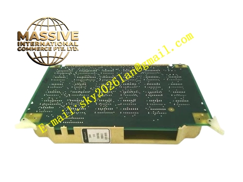
Honeywell 620-0085
Technical Specifications
- Output Channel Quantity: 8 form C relay output channels
- Relay Contact Rating: 250 VAC, 3 A resistive load per channel
- Channel Isolation: 1500 VAC optical isolation between coil drive circuit and backplane side
- Backplane Interface: IPC620 I/O Link backplane bus
- Operating Temperature: 0 °C to +60 °C
- Power Consumption: 4.8 W maximum
- Hot Swap Support: Yes
Functional Features Independent form C dry contact for each output channel. Contact feedback readback circuit compares actual contact state against command state. Contact weld fault alarm triggers when feedback mismatches control command. RC arc suppression network fitted to each relay contact for arc energy reduction. Per-channel LED indicator on front panel shows command output status. All output command frames carry CRC checksum before transmission.
Application Scenarios Solenoid valve drive for small interlock control loops Audible alarm horn and status beacon light control Pump and fan local start-stop relay control Auxiliary cabinet discrete load control with contact feedback diagnosis Spare relay output channel replacement for IPC620 control racks
Performance Parameters
- Relay mechanical life: 10,000,000 switching cycles without load
- Electrical life: 100,000 switching cycles under rated resistive load
- Pull-in time: 10 ms maximum, release time: 5 ms maximum
- Contact mismatch fault response: Less than 150 ms
Material Composition FR4 multilayer PCB, sealed miniature electromagnetic relays, optocoupler drive isolators, RC arc suppression components, TVS surge suppression diodes, current limiting resistors, gold-plated backplane edge connector, UL94 V0 flame retardant plastic front panel.
Structural Features Standard eurocard plug-in size matching IPC620 rack slot. Relay contact terminal block and channel LED indicators arranged on front panel. Internal isolation barrier separates low voltage drive logic area and high voltage load contact area. Relay components are spaced apart to reduce heat accumulation under full-load operation. Anti-keying notch prevents mis-insertion into analog input module slots.
Working Principle The IPC620 CPU sends on or off command through I/O Link backplane bus. Onboard logic circuit receives command and drives relay coil through isolated optocoupler circuit. Relay mechanical contact closes or opens to switch the external load circuit. Readback sampling circuit continuously detects actual contact state. If measured feedback state differs from issued command, contact weld fault flag is generated and uploaded to CPU.
Installation Requirements Confirm external load voltage and current stay within relay contact rated parameters. Install freewheeling diode or surge suppressor at inductive load terminals. Route relay load wiring separately from low voltage instrument signal cables. Enable contact readback diagnosis inside IPC configuration software. Test each channel action sequence after installation before putting process online.
Usage Notes Inductive loads accelerate relay contact erosion even within rated current limit. Contact weld fault cannot be cleared by software reset, the module requires replacement. Do not connect high voltage AC signal to low voltage backplane or logic terminals. Audible clicking sound during switching is normal mechanical operation of relay.







