



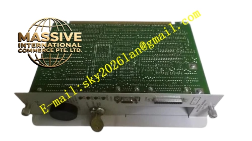
Description
Honeywell 620-1200
Technical Specifications
- Channel Count: 8 analog input channels
- Input Signal Range: 4-20 mA, 0-10 VDC configurable per channel
- Resolution: 16-bit ADC
- Channel Isolation: 500 VAC group isolation
- Backplane Interface: IPC620 I/O Link backplane bus
- Operating Temperature: 0 °C to +60 °C
- Power Consumption: 4.3 W maximum
- Hot Swap Support: Yes
Functional Features Per-channel signal range configuration in software. Open circuit detection for 4-20 mA two-wire transmitters. Programmable digital filter to smooth fluctuating measurement signals. Front panel LED indicates module power, communication and group fault status. Conversion data carries CRC checksum before upload to CPU. Over-range and under-range flag generation for each channel.
Application Scenarios Pressure transmitter signal collection Temperature transmitter 4-20mA signal acquisition Flow and level analog measurement input Chemical and oil-gas process variable monitoring
Performance Parameters
- Conversion accuracy: ±0.1 % full scale
- ADC sampling rate: 100 Hz per channel
- Isolation withstand voltage: 500 VAC for 60 seconds
- Fault detection response: Less than 200 ms for open loop
Material Composition Multilayer FR4 PCB, 16-bit ADC chip, signal conditioning operational amplifier, optocoupler isolation components, precision metal film sampling resistors, TVS surge suppression diodes, gold-plated backplane edge connector, UL94 V0 plastic front panel.
Structural Features Standard eurocard plug-in size for IPC620 rack. Front panel terminal block for field analog signal wiring. Internal isolation barrier separates field analog side and backplane digital logic. Anti-keying notch prevents mis-insertion into digital output slots. Analog signal traces adopt guarded layout to reduce noise interference.
Working Principle Field analog current or voltage signal enters the terminal block and passes through signal conditioning circuit. ADC chip converts analog quantity into 16-bit digital value. Onboard FPGA reads conversion result, judges over-range and open-circuit state, adds CRC checksum and transmits data frame to CPU through I/O Link bus. Digital filter algorithm suppresses high-frequency signal jitter.
Installation Requirements Use shielded twisted pair cable for analog signal wiring. Set signal type and engineering scaling parameters in configuration software. Calibrate zero and span on site according to transmitter range. Separate analog wiring from relay output power cables.
Usage Notes Do not input AC voltage to analog input terminals. Improper shielding grounding will increase measurement drift and noise. Overload voltage on input channel will damage sampling circuit.







