



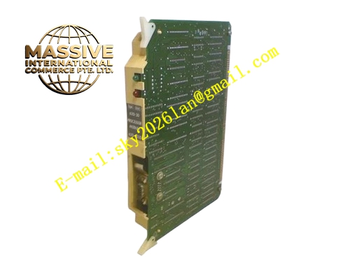
Description
Honeywell 620-1631
Technical Specifications
- Supported analog signals: 4–20 mA DC current, 0–10 V DC voltage
- Loop supply output: Regulated 24 V DC, 200 mA per signal group
- Signal isolation: 500 VAC reinforced isolation between backplane and field side
- Terminal rating: For 0.5–2.5 mm² stranded field cables
- Terminal torque rating: 0.4 N·m to 0.6 N·m
- Operating temperature: 0 °C to +60 °C
- Storage temperature: -40 °C to +85 °C
- Relative humidity: 5% to 95% non-condensing
- Mounting: Fixed to IPC620 rack lower terminal compartment
Functional Features Delivers stable 24 V DC loop power supply for two-wire field transmitters. Independent TVS surge absorption on every signal line, diverts electrostatic and lightning-induced transient voltage from field cables away from upstream analog input cards. On-board RC low-pass filter network suppresses high-frequency noise coupled from variable frequency drives and high-current power cables. Silk-screen labeling on each terminal clearly marks signal polarity, shielding ground points and channel numbers, reduces field wiring error rate. Built-in resettable fuse per loop, single-loop short circuit does not disrupt operation of remaining channels. Dedicated shielding ground bus bar collects shield wires from all field instrument cables, implements single-point cabinet grounding.
Application Scenarios Centralized field wiring interface for mixed analog signals from pressure, flow and temperature transmitters in chemical plants Cabinet terminal distribution for oil refinery flow measurement loops Pump and valve feedback signal termination for auxiliary interlock systems Field instrument wiring interface for remote water treatment instrument clusters Spare terminal unit replacement for aging IPC620 cabinet wiring racks Skid-mounted equipment control cabinet analog signal wiring assembly
Performance Parameters
- Loop supply regulation accuracy: ±1%
- Surge protection tolerance: ±8 kV contact electrostatic discharge
- Signal crosstalk attenuation: ≥65 dB
- Terminal contact resistance: ≤10 mΩ
- Insulation resistance: ≥1000 MΩ at room temperature
Material Composition Multilayer FR4 PCB substrate rated UL94 V0 flame retardant Tin-plated copper alloy screw terminals, oxidation and corrosion resistant TVS transient suppression diodes, precision metal film resistors Polyester filter capacitors, resettable fuses Powder-coated cold rolled steel mounting bracket Flame retardant nylon channel identification labels
Structural Features Flat rectangular PCB form factor, fits the lower terminal compartment of standard IPC620 racks. Multiple rows of screw terminals arranged on the front face for convenient field cable termination. Physical partition separating backplane low-voltage logic area and field signal area. Silk-screen printed channel number and signal definition labels aligned above each terminal. Wide copper power trace layout to minimize temperature rise under full load.
Working Principle Field transmitter cables are terminated to the front screw terminals. Signals first pass through the resettable fuse, surge absorption components, then RC filter network, before traveling through the rear flat cable to the upstream analog input module. The on-board voltage regulator generates stable 24 V DC supply for two-wire transmitters connected to the terminal blocks. Current monitoring circuits detect overcurrent, open-circuit and short-circuit faults on each signal group, and upload fault flags to the CPU when abnormal wiring conditions appear. Surge protection components absorb transient voltage spikes arriving via field instrument cables.
Installation Requirements Fully de-energize the control rack before board installation, wiring or configuration changes. Use shielded twisted pair cable for analog instrument wiring, ground the shield single-point inside the cabinet. Route analog signal terminals and high-current discrete output terminals in separate wiring zones. Disable unused loop power channels in configuration software to reduce standby power consumption. Verify 24 V DC output voltage with a multimeter before connecting field transmitters.
Usage Notes Never connect AC voltage signals to field signal terminals, high voltage will destroy on-board filtering components. Overloaded 24 V DC loop supply triggers current limiting and cuts power to the affected group. Double-point shield grounding introduces common mode noise and measurement deviation; maintain single-point ground. Do not daisy-chain multiple terminal adapter boards on a single field instrument cable run.







