



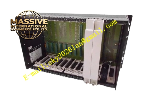
Description
Honeywell 620-1690
Technical Specifications
- Channel count: 16 independent digital input channels
- Supported signals: 24 V DC active switch, passive dry contact
- Signal isolation: 1500 VAC optical isolation matched to upstream input modules
- Debounce time: Fixed 20 ms hardware debounce
- Terminal rating: For 0.5–2.5 mm² stranded field cables
- Terminal torque rating: 0.4 N·m to 0.6 N·m
- Operating temperature: 0 °C to +60 °C
- Storage temperature: -40 °C to +85 °C
- Relative humidity: 5% to 95% non-condensing
Functional Features Independent current limiting resistor on each channel, limits input loop current to protect upstream optocoupler devices. Hardware RC debounce filter network eliminates mechanical contact bounce spikes, prevents false signal triggering. TVS transient suppression diodes absorb induced surge voltage from field cabling. Channel silk-screen labels align one-to-one with upstream input module channels, cuts field troubleshooting time. Grouped common terminal layout for neat, unified 24 V power return wiring. Dedicated shielding ground point collects shield wires from field switch cables.
Application Scenarios Limit switch and safety interlock signal collection for process valves Pump, fan and motor auxiliary contact feedback monitoring Pressure, level and flow switch status acquisition for alarm interlock loops Spare discrete input wiring unit for aging IPC620 control cabinets Conveyor and packaging machine travel limit signal termination
Performance Parameters
- Signal detection threshold: 18 V DC minimum for ON state, 5 V DC maximum for OFF state
- Debounce filter delay: Fixed 20 ms
- Surge tolerance: ±8 kV contact electrostatic discharge
- Insulation resistance: ≥1000 MΩ
- Channel crosstalk attenuation: ≥-60 dB
Material Composition FR4 flame retardant multilayer PCB substrate Tin-plated copper alloy screw terminals Metal film current limiting resistors, ceramic filter capacitors TVS transient suppression diodes Cold rolled steel powder-coated mounting bracket Nylon terminal identification labels
Structural Features Flat rectangular PCB form factor, compatible with IPC620 lower terminal compartment. Two rows of screw terminals on the front, split between signal and common contact zones. Rear flat cable connector mates directly to upstream digital input module. Physical partition between field 24 V signal area and backplane logic area. Channel silk-screen labels printed above each terminal position.
Working Principle Field switch contact cables are terminated to the input terminals. The 24 V DC signal travels through the current limiting resistor and optocoupler input side of the upstream module, converting field voltage signal to isolated logic level. Hardware debounce filter network rejects fast transient state changes caused by mechanical contact bounce. Open-wire detection circuit identifies open circuit conditions by monitoring input loop leakage current level. Processed channel state data is packaged into I/O Link bus frames and uploaded to the IPC620 CPU.
Installation Requirements Use twisted pair cable for field switch wiring. Route discrete input wiring separately from high-current relay output cabling. Set debounce time matching mechanical switch characteristics in configuration software. Verify channel state changes synchronously with field switch actuation during commissioning. Tighten all terminal screws to rated torque to avoid loose connections.
Usage Notes Never connect high-voltage AC directly to digital input terminals. Long field cable runs increase induced noise risk and false triggering. Debounce time set too short causes unstable state readings for aged mechanical switches. Do not modify on-board current limiting resistors for input channels.







