



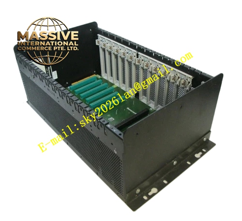
Description
Honeywell 620-3691
Technical Specifications
- Channel count: 24 independent digital input channels
- Supported signals: 24 V DC active switch, passive dry contact
- On-board indication: 1 red LED per channel, illuminates when the circuit is closed
- Terminal rating: For 0.34–1.5 mm² small-gauge stranded cables
- Terminal torque rating: 0.25 N·m to 0.35 N·m
- Signal isolation: 500 VAC group isolation matched to upstream digital input modules
- Operating temperature: 0 °C to +60 °C
- Storage temperature: -40 °C to +85 °C
- Relative humidity: 5% to 95% non-condensing
Functional Features Independent current limiting resistor on each channel, limits input loop current to 10 mA to protect upstream digital input optocoupler devices. On-board LED connected directly across the signal loop, brightness scales proportionally with input voltage for reliable status visibility. Hardware RC debounce filter network eliminates mechanical contact bounce spikes, prevents false signal state triggering. TVS transient suppression diodes absorb induced surge voltage and electrostatic discharge arriving via field cabling. Channel silk-screen labels align one-to-one with upstream input module channel numbers, cuts field wire tracing workload. Grouped common terminal layout for neat, unified 24 V power return wiring.
Application Scenarios Dense limit switch signal collection for packaging and conveyor lines Pump and fan auxiliary contact, valve position feedback signal wiring Small PLC control cabinet high-density discrete signal input interface Legacy control cabinet terminal block aging, limited space retrofit projects High-frequency inspection chemical and water treatment workshop discrete signal status visualization upgrades
Performance Parameters
- Signal detection threshold: 18 V DC minimum for ON state, 5 V DC maximum for OFF state
- Hardware debounce delay: Fixed 15 ms
- LED operating current: 5–8 mA
- Surge tolerance: ±8 kV contact electrostatic discharge
- Insulation resistance: ≥1000 MΩ at room temperature
- Channel crosstalk attenuation: ≥-62 dB
Material Composition FR4 flame retardant PCB substrate, UL94 V0 rated Tin-plated copper alloy cage clamp screw terminals Red through-hole light-emitting diodes Metal film current limiting resistors, ceramic filter capacitors TVS transient suppression diodes Nylon channel identification labels Powder-coated cold rolled steel mounting bracket
Structural Features Narrow form factor flat PCB, designed for high-density cabinet mounting positions. Two compact rows of screw terminals on the front face, channel number silk-screen printed adjacent to each terminal and LED. Rear flat cable connector mates directly to the upstream 24-channel digital input module. Mounting holes on the board edge for locking to the cabinet DIN rail. Physical partition between signal loop area and LED indicator circuit area, prevents indicator failure from disrupting signal transmission. Silk-screen marking clearly labels common power terminal polarity.
Working Principle Field switch contact cables are terminated to the front terminals. The 24 V DC signal splits into two paths after passing through the current limiting resistor: one path travels through the RC debounce network to the upstream digital input module for signal acquisition, the other path powers the on-board LED to provide visible channel status indication. TVS components continuously divert surge voltage arriving via field cables, blocking high voltage from entering upstream modules. The debounce network filters high-frequency jitter from mechanical contact bounce, ensuring stable, non-transient signal state readings for the control system.
Installation Requirements De-energize the cabinet 24 V control power before wiring. Pre-crimp ferrules on small-gauge cables before termination, prevent stray strands bridging adjacent terminals. Route discrete signal cables in dedicated cable trays, separated from high-current VFD and contactor power wiring. Terminate all common terminals to the cabinet 24 V power return bar, ensure tight, low-resistance connections. Confirm board seating on the mounting rail, no movement or flex under applied cable tension.
Usage Notes Never connect AC high voltage to digital input terminals, high voltage will destroy on-board components and upstream input cards. LED brightness dimming over long operation is normal, it does not affect signal transmission function. Tighten terminals semi-annually in high-vibration cabinet environments to prevent loose connections. Do not replace on-board current limiting resistors with mismatched values, this causes LED brightness error and input threshold drift.







