



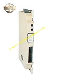
Description
Honeywell 621-0010
Technical Specifications
- Slot count: 4 dedicated slots (CPU slot, power supply slot, communication expansion slot, debug slot)
- Bus type: 621 proprietary parallel I/O bus
- Backplane power: 5 V DC backplane logic bus, 24 V DC field power bus
- Mounting method: Screw-fixed to cabinet uprights
- Operating temperature: 0 °C to +60 °C
- Backplane withstand voltage: 500 VAC
Functional Features Gold-plated bus finger contacts, reliable long-term insertion contact without oxidation. Anti-keying slot design, prevents incorrect insertion of CPU or power supply modules. Integrated bus termination resistors, eliminates high-speed signal reflection at the bus end. Dedicated grounding posts, provides a unified collection point for module shielding grounds. Separate power and signal bus traces, prevents power noise coupling into signal circuits. Reserved expansion connector, supports connection to remote I/O expansion racks.
Application Scenarios Main rack mounting base for 621 series PLC systems Spare part replacement for corroded, oxidized backplanes in legacy 621 cabinets Base component for new control cabinet assembly Main rack replacement for control system capacity expansion retrofits
Performance Parameters
- Gold finger plating thickness: 30 microinch
- Bus signal reflection attenuation: ≥-25 dB
- 5 V DC bus current rating: 20 A continuous
- Insulation resistance: ≥2000 MΩ
- Slot insertion life: 500 mating cycles
Material Composition Thick FR4 PCB substrate Gold-plated bus edge fingers Precision termination resistor network Brass grounding posts Powder-coated cold rolled steel mounting brackets Flame retardant PCB solder mask
Structural Features Long rectangular thick PCB, corresponding guide slots aligned for each module position. Rear mounting holes for fixation to cabinet uprights. Gold-plated fingers aligned to every module slot position. Reserved expansion interface on the backplane side edge. Silk-screen labeling marks each slot function, prevents incorrect module insertion.
Working Principle Parallel copper traces on the backplane connect the finger contacts of all installed slots. After the CPU module is inserted, it communicates with the power supply and communication modules through the gold finger backplane bus. The 5 V DC power bus distributes supply power to all plugged-in modules, while the 24 V DC field power bus runs through all slots to provide field loop power for terminal connections. On-board termination resistors absorb high-speed signal reflection at the bus end, ensuring stable high-speed communication signals.
Installation Requirements Mount the backplane flat, no twisting or deformation. Tighten mounting screws in diagonal order, avoid PCB stress cracking. Connect grounding posts reliably to the cabinet protective ground. Align modules with slot guides during insertion, press evenly until gold fingers are fully seated.
Usage Notes When cleaning oxidized gold fingers, use a rubber eraser — never sand or abrade the gold plating layer. Never hot-swap the CPU module while rack power is live, this causes bus communication interruption. Maintain safe clearance between the backplane and cabinet door, avoid pinching the PCB when closing the door.







