



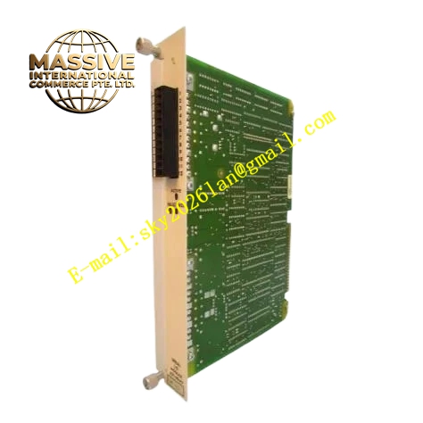
Description
Honeywell 621-9934C
Technical Specifications
- Channel count: 8 independent RTD input channels
- Supported sensors: PT100, PT1000 resistance temperature detectors
- Wiring mode: Software configurable 3-wire, 4-wire connection
- Measurement range: -200 °C to +850 °C
- Resolution: 0.01 °C
- Coating dielectric strength: 10 kV/mm
- Salt mist resistance: Compliant with IEC 60068-2-11 salt spray test standard
- Operating temperature: -10 °C to +65 °C
- Backplane interface: 621 parallel I/O bus
- Hot swap support: Yes
Functional Features On-board precision constant current source circuit supplies stable excitation current to RTD sensors, eliminates measurement error from excitation current fluctuation. 3-wire lead resistance compensation algorithm, automatically cancels temperature deviation introduced by long lead wire resistance. Independent per-channel open-circuit and short-circuit diagnosis, triggers channel fault alarm for disconnected sensors. Software-configurable temperature unit, switchable between Celsius and Fahrenheit. Programmable digital filter smooths temperature readings, suppresses signal jump caused by industrial electromagnetic interference. All acquired temperature values and fault flags carry CRC checksum for upload integrity verification. Acrylic conformal coating blocks moisture, salt mist and corrosive vapor from contacting PCB traces for long-term operation in harsh environments.
Application Scenarios Bearing and pipeline temperature monitoring on offshore platforms Reactor and heat exchanger temperature measurement in coastal chemical plants Basin and pipe temperature monitoring in wastewater treatment facilities Spare part replacement for corrosion-prone temperature input channels in pulp and chemical processing plants Temperature acquisition loops in high-dust, high-condensation industrial environments
Performance Parameters
- Temperature measurement accuracy: ±0.1 °C
- Sample rate: 20 Hz per channel
- Common mode rejection ratio: ≥90 dB
- Open circuit detection response: ≤250 ms
- Coating insulation resistance: ≥10000 MΩ
- Mold resistance: Compliant with GB/T 2423.16 long mold growth test standard
Material Composition FR4 low-noise multilayer PCB substrate Transparent acrylic conformal coating layer High-precision 16-bit ADC chip Constant current source excitation circuit Optocoupler isolation devices Ultra-stable precision reference resistor array TVS surge protection diodes Gold-plated backplane edge finger connector UL94 V0 flame retardant plastic front panel
Structural Features Standard Eurocard plug-in dimensions for 621 rack I/O slots. Front screw terminals silk-screened with RTD wire connection definitions. Rear gold fingers mate directly to the backplane bus. Isolation barrier separates sensor field side and backplane logic side. Constant current measurement traces are fully shielded to reduce thermal drift. PCB surface and component leads fully covered by uniform thin conformal coating, gold-plated connector contacts left uncoated.
Working Principle The on-board precision constant current source injects stable small current into the RTD sensor. The ADC circuit measures voltage drop across the RTD and lead wires, the compensation algorithm removes lead resistance influence and calculates actual RTD resistance value. The resistance-to-temperature conversion formula outputs real-time process temperature. Loop impedance monitoring circuit identifies sensor open circuit or short circuit faults and generates fault flags. Processed temperature data is packaged into bus frames and uploaded to the PLC CPU. The conformal coating forms a continuous insulating barrier over PCB traces and component pins, blocking moisture, salt particles and corrosive gas from creating conductive leakage paths between adjacent circuits.
Installation Requirements Follow 3-wire or 4-wire RTD wiring standards strictly. Use shielded compensation cable for RTD sensor runs, single-point shield grounding inside the cabinet. Configure sensor type and wiring mode per channel in software. Calibrate zero and span on site after installation. Avoid scratching the PCB conformal coating surface during handling and installation.
Usage Notes Never connect AC voltage signals to RTD input terminals, high voltage will damage the measurement circuit. Scratches in the conformal coating layer reduce corrosion protection performance; severely damaged units require full module replacement. Do not use solvent cleaners directly on the coated PCB surface, this dissolves the acrylic coating. Long lead runs with excessive resistance increase measurement error, use thicker gauge cable for long-distance sensor wiring.







