



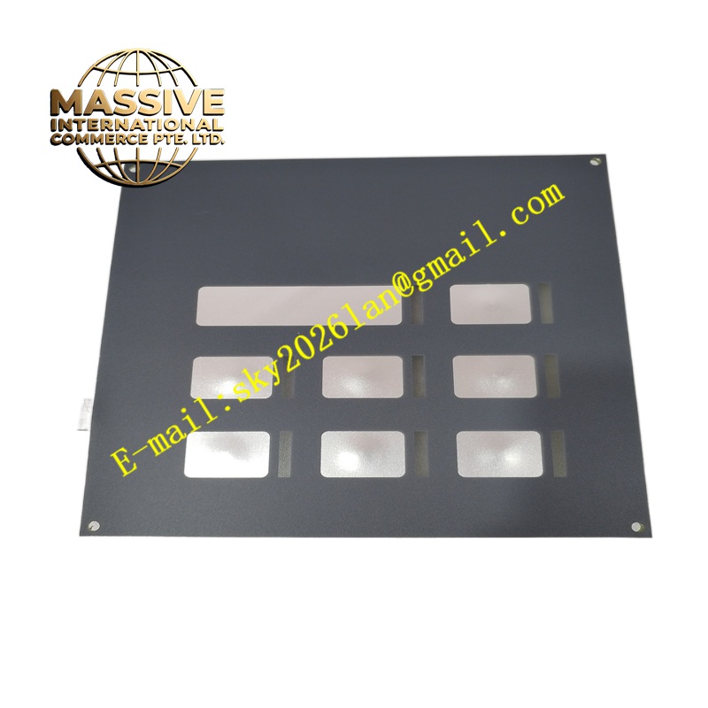
Description
Honeywell 6580100019
Technical Specifications Flame signal amplification and filtering; flame strength analog output; flame present relay contact output; configurable flame detection sensitivity; 24V DC power supply; self-check fault detection circuitry.
Functional Features Amplifies low-level optical signals received from the matched flame sensor. Filters out background light, furnace hot refractory radiation and electrical interference signals. Compares processed flame signal strength against user configured threshold values to determine flame status. Activates the flame present relay when valid flame radiation is detected. Triggers fault alarm outputs for sensor failure, wiring breaks or internal amplifier malfunctions.
Application Scenarios Industrial boiler burner management systems, furnace combustion safety monitoring, gas and oil burner flame detection, thermal oxidizer safety interlock systems.
Performance Parameters Adjustable flame sensitivity threshold; fast flame loss response time; high rejection of false flame signals from hot refractory; stable operation under high cabinet ambient temperature.
Material Composition Housing is flame-retardant thermoplastic or coated metal; internal signal processing PCB is FR-4 flame-retardant substrate; signal amplification components are precision analog semiconductors; terminal block conductors are nickel-plated copper alloy.
Structural Characteristics Compact rectangular enclosure designed for cabinet mounting; front panel with flame strength indicator and status LEDs; screw terminal blocks for sensor wiring, power supply and flame relay output connections; internal potentiometers or configuration jumpers for sensitivity adjustment.
Working Principle The optical flame sensor converts flame ultraviolet or infrared radiation into a low-level electrical signal. This signal is sent to the amplifier assembly. The amplifier filters and amplifies the signal and compares the measured flame signal magnitude with the set detection threshold. When the signal exceeds the threshold, the flame present relay energizes and sends confirmation to the burner control system. Continuous internal diagnostics monitor sensor wiring and amplifier hardware integrity.
Installation Requirements Mount the amplifier inside a clean, cool control cabinet separate from the high-temperature combustion area. Run dedicated shielded cable between the amplifier and the flame sensor. Set flame detection sensitivity according to the furnace and burner operating characteristics. Test flame detection and flame loss trip functions during burner commissioning.
Precautions for Use Route sensor cable away from ignition transformer and high-voltage ignition wiring. Perform regular flame signal testing as part of burner safety maintenance schedules. Replace the assembly when it fails to respond reliably to verified flame conditions.







