



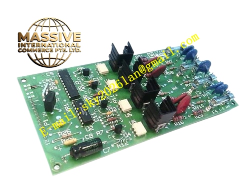
Description
Honeywell 82408458-002
Technical Specifications
- Input power: 24 V DC
- Fan output: 12 V DC, 2 A maximum drive current
- Speed monitoring: 1-channel fan tachometer pulse input
- Fault output: Passive dry contact, actuates on fan stop
- Operating temperature: 0 °C to +60 °C
- Mounting: Screw-fixed in the cabinet fan compartment
Functional Features DC-DC regulated output, supplies stable 12 V DC to the cooling fan. Tachometer pulse monitoring, triggers alarm contact actuation when fan speed drops or fan stops. Overcurrent protection, automatically cuts output when fan lockup occurs. On-board LED indicates power normal and fan run status for easy inspection. Compact terminal layout, fits the narrow fan compartment space.
Application Scenarios Power supply and monitoring for TDC3000 cabinet cooling fans Spare part replacement for fan power board burnouts and false fan alarms Repair of fan speed monitoring circuits in legacy TDC3000 cabinets Cooling system upgrades for high-ambient-temperature control rooms
Performance Parameters
- Output regulation accuracy: ±2%
- Overcurrent protection threshold: 2.2 A
- Alarm contact rating: 24 V DC, 0.3 A
- Standby quiescent current: ≤10 mA
- Speed monitoring response time: ≤200 ms
Material Composition FR4 PCB substrate DC-DC regulator chip Optocoupler isolation drive devices Reed alarm relay TVS surge protection diodes Screw wiring terminals
Structural Features Long narrow PCB form factor. Front face houses power input, fan output and alarm output terminals. Status LEDs indicate power and fan operating state. Mounting holes for screw fixation in the fan compartment bracket.
Working Principle Cabinet 24 V DC power connects to the drive board, passing through the DC-DC regulator circuit to produce stable 12 V DC output for the cooling fan. Fan tachometer pulse signals feed into the monitoring circuit; when pulses stop or frequency drops below threshold, the on-board reed relay contact actuates, sending a fan fault dry contact signal to the DCS alarm system. Fan lockup overcurrent triggers the regulator current limiting circuit, cutting output power to protect the board and fan.
Installation Requirements Connect 24 V DC supply and fan wiring strictly per terminal marking. Wire alarm contact signals into the DCS fan alarm input channel. Mount the board on the fan compartment bracket, do not block the fan airflow path. Verify LED status after power-up, confirm fan operates at rated speed.
Usage Notes Total fan current must not exceed the 2 A drive rating; overload triggers overcurrent protection. Broken tachometer wire causes false fan fault alarms; check wiring regularly. Never adjust output voltage above 12 V DC, this causes fan overvoltage failure. Clear mechanical lockup causes before resetting the drive board protection after an overcurrent trip.







