



Description
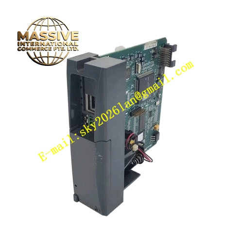
Honeywell 900C32-0021
Technical Specifications
- Integrated I/O: 8 universal analog/digital inputs, 6 24 V DC transistor outputs
- Processor: 32-bit industrial CPU
- User program memory: 16 KB
- Data memory: 4 KB
- Communication interfaces: 1 RS485 port, 1 Ethernet port
- Supported protocols: Modbus RTU, Modbus TCP
- Supply power: 24 V DC
- Operating temperature: 0 °C to +60 °C
- Expansion capacity: Up to 3 expansion I/O racks
Functional Features Integrated 8 PID loops, supports cascade and ratio control. Dual communication interfaces for connection to upper HMI and SCADA systems. On-board LCD display and operation keys, supports local status viewing without external programming devices. Super capacitor backup for RAM data, maintains data retention during power loss. Supports online program download and variable force debugging. Front panel LEDs indicate run, fault and communication status. Built-in real-time clock for event timestamping.
Application Scenarios Automatic control for small heat exchange stations and boiler feed units Water treatment dosing and filtration unit PLC control Conveyor line and packaging machine equipment control Spare part replacement for legacy HC900 system CPU faults
Performance Parameters
- Logic scan cycle: 1 ms per 1 KB program
- PID regulation accuracy: 0.1% full scale
- Communication response time: ≤10 ms
- Data retention time: 7 days after power loss
- Real-time clock accuracy: ±2 seconds per day
Material Composition ABS flame retardant plastic enclosure 32-bit industrial CPU chip Flash memory and RAM chips Super capacitor backup circuit RS485 and Ethernet isolation transformers Gold-plated screw terminals Flame retardant PCB main board
Structural Features Long rectangular DIN-rail mount form factor. Front panel features LCD display, 4 operation keys and status LED array. Side expansion interface connects to I/O racks. Bottom section houses 24 V power and field I/O wiring terminals. DIN rail clip for quick cabinet installation.
Working Principle On power-up, the CPU loads user control program from flash memory into RAM, entering cyclic scan mode. In each scan cycle, the unit reads integrated input terminal states and expansion rack I/O data, executes user logic and PID computation, then writes output values to corresponding I/O modules. The RS485 and Ethernet ports exchange data with upper HMI and SCADA systems via Modbus protocol. The hardware watchdog continuously monitors program execution; if program runaway is detected, the system resets and places outputs in safe state.
Installation Requirements Clip the CPU unit directly to the cabinet DIN rail. Connect 24 V DC supply with correct polarity, reversed connection damages the unit. Connect expansion racks to the CPU via dedicated flat expansion cable. Set communication address and time parameters via front panel keys after power-up. Download matching user program during commissioning.
Usage Notes 24 V supply fluctuation exceeding ±20% causes unexpected CPU reset. The super capacitor ages over time; replace every 5 years to avoid RAM data loss after power outage. Never hot-swap expansion rack cabling during operation, this causes I/O status fluctuation and equipment misoperation. Program download interrupts current control logic; schedule downloads during equipment shutdown.







