



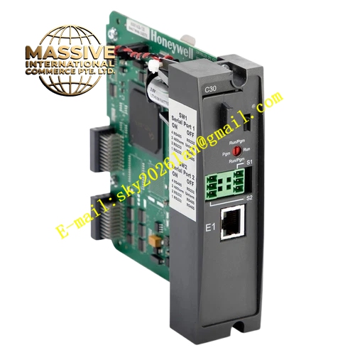
Description
Honeywell 900C32-0142
Technical Specifications
- Channel count: 8 analog input channels
- Signal type: 4–20 mA, 0–10 V DC, software configurable per channel
- Resolution: 16-bit ADC
- Channel isolation: 500 VAC group isolation
- Supply power: 5 V DC from rack backplane
- Operating temperature: 0 °C to +60 °C
- Update cycle: 20 ms full-channel scan
Functional Features Per-channel independent signal range configuration, compatible with different transmitter outputs. 4–20 mA loop wire break diagnosis, triggers channel alarm when transmitter circuit opens. Digital filter smooths measurement readings, suppresses signal jump from field electromagnetic interference. On-board LED indicates module power, communication and overall fault status. All acquired data carries CRC checksum for upload integrity. Automatic over-range and under-range flagging, uploaded to the CPU for alarm processing.
Application Scenarios Pressure transmitter signal acquisition Temperature transmitter 4–20 mA signal collection Flow and level analog measurement input Process variable monitoring for chemical and oil-gas installations Spare part replacement for legacy HC900 analog input channel faults
Performance Parameters
- Conversion accuracy: ±0.1% full scale
- Common mode rejection ratio: ≥80 dB
- Wire break detection response: ≤200 ms
- Temperature drift: ±25 ppm/°C
- Channel crosstalk: ≥-65 dB
Material Composition FR4 PCB substrate 16-bit ADC chip Instrumentation operational amplifier Optocoupler isolation devices Precision metal film sampling resistors TVS surge protection diodes Gold-plated backplane connector ABS flame retardant enclosure
Structural Features Long rectangular DIN-rail mount module. Front screw terminals silk-screened per channel number. Rear gold fingers mate directly to the expansion rack backplane. Isolation barrier separates field signal side and backplane logic side. Shielded layout for analog traces, reduces noise interference.
Working Principle Field analog signals connect to input terminals, pass through signal conditioning circuit and amplifier to the 16-bit ADC, which converts analog values to digital data. On-board logic judges signal range and open-loop status, packages converted values and fault flags into communication frames, sent to the CPU via the backplane bus. Digital filter algorithm smooths acquisition values, suppresses high-frequency interference.
Installation Requirements Use shielded twisted pair for analog signal wiring, single-point shield grounding. Configure signal type and engineering scale parameters per channel in software. Route analog cables separately from power cabling trays. Calibrate zero and span on site after installation.
Usage Notes Never connect AC voltage signals to analog input terminals, high voltage damages the ADC chip. Improper shield grounding causes measurement drift and noise. Overload voltage on input channels damages sampling circuits.







