



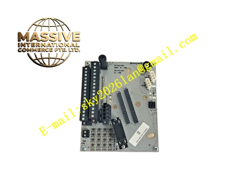
Description
HONEYWELL CC-PCNT01
Technical Specifications Backplane power supply from C300 rack Multi-channel pulse input interface Support high frequency pulse signal sampling Opto-electrical isolation for each input channel Hardware pulse debounce function Rack plug-in design compatible with C300 I/O rack
Functional Features Capture pulse signal from field pulse generating instruments Calculate pulse frequency and accumulated pulse total value Convert pulse data into engineering value for controller use Electrically isolate field instrument circuit and DCS control circuit Filter signal noise and interference pulse to avoid false counting Upload module hardware fault and channel signal loss alarm to DCS operator station
Application Scenarios Petrochemical, water treatment and power plant Experion PKS C300 DCS cabinets Flow totalization measurement for turbine flow meters Rotating speed monitoring of rotating machinery Energy metering and batch counting process
Performance Parameters Operating temperature range 0℃ to 60℃ Relative humidity 5% to 95%, non-condensing High pulse sampling frequency High channel isolation voltage Meet industrial EMC anti-interference requirements
Material Composition FR-4 multilayer printed circuit board Gold-plated backplane edge connectors High-speed counting chips Optocoupler isolation components Signal filter resistors and capacitors Flame retardant anti-static plastic front panel
Structural Features Standard rack plug-in card structure Front panel fitted with LED indicators for power, running and fault status Rear gold fingers connect rack backplane bus Anti-reverse insertion positioning notch Model marking printed on card surface Work with matched FTA terminal base for field instrument wiring
Working Principle Pulse signal from field meter enters module through FTA terminal base. Optocoupler isolates field circuit and control circuit. High-speed counting chip captures rising or falling edge of pulse signal, accumulates pulse number and calculates real-time pulse frequency. Calculated measurement data transfers to C300 controller via backplane bus. Diagnostic circuit continuously monitors channel signal status and sends alarm when signal loss occurs.
Installation Requirements Wear anti-static wrist strap during installation and removal Insert card fully into rack slot and tighten fixing screw Complete wiring connection with field pulse instruments on FTA terminal base Cabinet protective grounding must be qualified Shield cable used for field pulse signal wiring and single point grounding Verify hardware version compatibility with C300 firmware
Precautions for Use Do not plug or unplug the module under power-on state Set pulse edge type and sampling parameter in engineering station after installation Check field instrument pulse output type before wiring Inspect shield cable connection and terminal tightness periodically Avoid running pulse signal cable alongside high voltage power cable







