



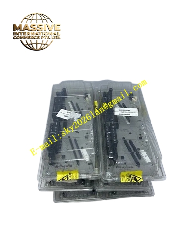
Description
HONEYWELL CC-TDOB11
Technical Specifications:
- Brand: Honeywell
- Model: CC-TDOB11
- Part Number: 51308373-175
- Product Type: Redundant Digital Output I/O Terminal Board
- Compatible System: Honeywell C300 Control System
- I/O Type: Digital Output
- Channels: 32 channels
- Voltage: 24V DC
- Configuration: Redundant
- Architecture: IOTA (I/O Termination Assembly)
- Bus Type: 24V Bus
- Origin: United States
Functional Features:
- Redundant Configuration: Supports redundant operation for enhanced reliability
- 32-Channel Digital Output: Provides 32 channels of 24V digital output
- IOTA Architecture: Compatible with Honeywell C300 IOTA system
- 24V Bus Design: Integrated 24V bus for power distribution
- Field Device Interface: Connects field devices to C300 controller
- High Availability: Redundant design minimizes downtime risk
- Easy Maintenance: Modular design facilitates easy replacement
- Industrial Grade: Designed for harsh industrial environments
- Status Indication: LED indicators for channel and redundancy status
- Compatible with CC-PDOB01: Works with CC-PDOB01 DO module
Application Scenarios:
- Critical process control systems
- Safety instrumented systems
- Petrochemical process automation
- Oil and gas production control
- Power generation control systems
- Pharmaceutical manufacturing
- Any application requiring redundant digital output
- C300 controller-based systems
- High availability control applications
Performance Parameters:
- Channel Count: 32 digital output channels
- Output Voltage: 24V DC
- Configuration: Redundant operation
- Response: Fast digital output switching
- Reliability: Redundant design for continuous operation
- Compatibility: C300 IOTA architecture
Material Composition:
- Industrial grade printed circuit board
- High-quality electronic components
- Precision terminal blocks
- Durable housing materials
- Status indicator LEDs
- Redundancy communication components
- Protective enclosure for industrial environments
- Quality connectors and wiring terminals
Structural Features:
- Modular IOTA form factor
- 32-channel terminal block connections
- Redundant communication interface
- Status indicator LEDs for each channel
- 24V bus connections
- DIN rail or chassis mounting
- Compact design for control cabinet installation
- Clear channel labeling
- Ventilation for thermal management
- Protective housing
Working Principle:
The CC-TDOB11 terminal board serves as the interface between the C300 controller’s digital output module (CC-PDOB01) and field devices. In redundant configuration, two terminal boards work together to provide continuous digital output capability. The board receives digital output commands from the controller through the IOTA backplane, processes these commands, and switches the corresponding output channels to control field devices such as relays, solenoid valves, indicators, and actuators. The redundant design ensures that if one path fails, the other maintains control continuity. The 24V bus distributes power to the output channels, and status indicators provide visual feedback on channel and redundancy status.
Installation Requirements:
- Install in compatible Honeywell IOTA chassis
- Pair with CC-PDOB01 digital output module
- Ensure proper connection to system backplane
- Follow Honeywell redundancy configuration guidelines
- Connect field wiring according to terminal diagrams
- Maintain adequate ventilation around the module
- Ensure proper grounding of the chassis
- Install in a clean, dry environment within specified temperature range
Precautions for Use:
- Installation should be performed by qualified system technicians
- Verify redundancy configuration before placing system in service
- Regularly monitor redundancy status through system diagnostics
- Ensure both redundant paths are properly synchronized
- Keep the module clean and free from dust and contamination
- Follow proper shutdown procedures before maintenance
- Verify field wiring connections are secure
- Monitor status indicators for fault conditions
- Document redundancy configuration for troubleshooting reference
- Replace fuses as specified if output faults occur







