



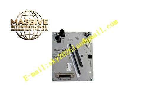
Description
Honeywell CC-TDOR01
Technical Specifications Multi-channel 24VDC digital output termination; each channel equipped with transient suppression components; rated field load voltage 24VDC; power supplied by rack backplane; operating temperature 0℃ to 60℃; storage temperature -40℃ to 85℃; relative humidity 5% to 95% non-condensing; non-redundant single IOM matching; rack slot mounting; UL and CE certification.
Functional Features It collects field actuator wiring to labeled screw terminal blocks. It suppresses back EMF surge generated by inductive loads such as solenoid coils. It receives on-off control signal from matched digital output IOM module and routes signal to field loads. It supports channel short-circuit fault diagnosis reported by IOM card. It provides orderly wiring layout to simplify cabinet maintenance.
Application Scenarios Auxiliary solenoid valve wiring termination for chemical plant non-critical control loops; local indicator light signal junction for refinery auxiliary cabinets; fan auxiliary relay control termination for power plant non-interlock loops.
Performance Parameters Surge protection components do not affect normal on-off output state; terminal contact performance is stable in long-term continuous operation; fault information upload matches controller scan cycle.
Material Composition Base housing adopts flame-retardant PC engineering plastic; internal circuit board is FR4 PCB with conformal coating; terminal conductive parts and screws are tin-plated copper alloy; transient suppression semiconductor devices are industrial grade; backplane connector pins are gold-plated.
Structural Characteristics Single-width rack termination base; front panel with numbered screw terminals and channel function marking; rear single backplane connector for one digital output IOM card; fool-proof keying structure to avoid mismatched IOM insertion; side elastic latches for rack rail locking.
Working Principle Control signal generated by digital output IOM module transmits to CC-TDOR01 through backplane connector. The signal passes through surge suppression circuit and reaches field solenoid or relay loads via screw terminals. When inductive load cuts off power, the suppression component absorbs reverse voltage spike and protects IOM output circuit. The IOTA does not generate control logic and only realizes wiring and signal protection.
Installation Requirements Install the termination base on Series C rack rail. Confirm keying notch matches non-redundant digital output IOM module. Use shielded cable for field inductive load wiring. Separate output cables and analog measurement cables. Torque terminal screws according to official torque specification.
Usage Notes Do not connect high-current AC loads directly to the output terminals. Verify coil voltage rating of field solenoid before power-on. Wear anti-static wrist strap during IOM card replacement. Do not energize incompatible signal types to the terminal blocks.







