



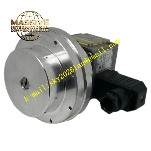
Description
Honeywell DDCM252
Technical Specifications
- Onboard I/O: 8 universal analog inputs, 4 digital outputs, 2 analog outputs
- Communication: BACnet MS/TP RS485
- Supply voltage: 24 V AC
- Program memory: 64 KB user logic
- Operating temperature: 0 °C to +50 °C
- Mounting: DIN rail mount
Functional Features Standalone operation without a central supervisor, executes control logic locally on power-up. Universal analog inputs, software configurable for 0–10 V, 4–20 mA or NTC thermistor signals. Trend logging function, stores 7 days of process data onboard. Schedules weekly timed control events, runs equipment on scheduled occupancy. BACnet MS/TP integration, connects to building management systems. Configure via hand-held tool or laptop software.
Application Scenarios Air handling unit sequence control Domestic hot water temperature regulation Pump station alternating lead/lag control Small process equipment standalone control Spare part replacement for failed legacy DDC controllers
Performance Parameters
- Logic scan cycle: 100 ms
- Communication baud rate: 38.4 kbps maximum
- Analog input accuracy: ±0.2% full scale
- Digital output rating: 1 A / 24 V AC per channel
- Battery-backed RAM retention: 5 years
Material Composition ABS flame retardant housing DIN rail mounting clip Plug-in screw terminal blocks Epoxy PCB RS485 isolation circuit
Structural Features Long rectangular DIN-rail mount housing. Front status LEDs for power, communication and I/O activity. Removable terminal blocks for field wiring. Side communication port connects to configuration tool. Mounting clip locks directly to standard 35 mm DIN rail.
Working Principle After power-up, the controller loads the user program from non-volatile memory, entering cyclic scan mode. Each scan reads analog and digital input states, executes user control logic, then writes outputs to drive connected equipment. The real-time clock runs scheduled occupancy events, starting and stopping equipment per the weekly timetable. The BACnet port exchanges process data and setpoints with the central building management system. The onboard trend log records process values at set intervals for later review.
Installation Requirements Clip the module to the cabinet DIN rail. Connect 24 V AC supply, verify polarity. Wire field sensors and actuators to labeled terminal blocks. Connect RS485 BACnet bus to the communication port, set node address and baud rate. Download the control program via configuration tool.
Usage Notes Never apply 230 V AC to 24 V digital output terminals, this destroys the output driver. RS485 bus termination resistor required at the far end of the bus segment. Program memory loses data if the backup battery ages; replace battery every 5 years. Do not mount the controller near high-voltage contactors, EMI causes communication errors.







