



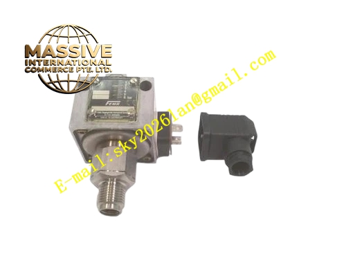
Description
Honeywell DNS06-201
Technical Specifications
- Pressure range: 0.5 to 6 bar adjustable setpoint
- Switch type: SPDT snap action contact
- Contact rating: 5 A / 250 V AC
- Pressure connection: 1/4 inch NPT male thread
- Electrical connection: Screw terminal block
- Repeatability: ±2% of setpoint
- Protection rating: IP54
Functional Features Field-adjustable setpoint via internal adjustment screw. Differential gap adjustment, sets the pressure difference between switch-on and switch-off points. Snap action contact, clean switching even at low differential pressure. Brass pressure port, compatible with air, water and non-corrosive gas. Manual test lever, allows contact simulation for maintenance testing. Status flag shows switch actuation position.
Application Scenarios Water pump low-pressure protection Compressor high-pressure cutout Gas burner supply gas pressure proving Hydraulic system pressure interlock Spare part replacement for failed pressure switches in process loops
Performance Parameters
- Maximum overpressure: 20 bar burst pressure
- Switching life: 100,000 operations
- Operating temperature: -20 °C to +85 °C
- Differential range: 0.1 to 1 bar adjustable
- Insulation resistance: ≥100 MΩ
Material Composition Brass pressure sensing element Stainless steel diaphragm Zinc-plated steel housing Bakelite terminal cover Silver alloy switch contacts Brass pressure fitting
Structural Features Round cast zinc housing. Bottom 1/4 inch NPT pressure port connects to process piping. Top terminal cover encloses electrical wiring. Side manual test lever. Status flag visible through the housing window.
Working Principle Process pressure connects to the brass port, acting on the stainless steel diaphragm. Diaphragm deflection moves a spring-loaded pushrod; when pressure reaches the user-set threshold, the pushrod trips the snap action mechanism, switching the SPDT contact state. As pressure falls below setpoint minus differential gap, the mechanism resets, switching contacts back. The adjustment screw changes pre-load on the spring, raising or lowering the activation pressure threshold.
Installation Requirements Screw the pressure port into the process tapping, use appropriate thread sealant. Mount the switch vertically, with the pressure port facing downward to prevent sediment buildup. Set activation pressure and differential via the internal adjustment screw. Test switch actuation by varying process pressure, confirm contact state changes correctly.
Usage Notes Maximum process pressure must not exceed the 20 bar rating, overpressure ruptures the diaphragm. Never adjust setpoint outside the 0.5–6 bar range, this damages the spring mechanism. Tighten the terminal cover screws to maintain IP54 seal. For gas service, leak-test all threaded connections after installation.







