



Description
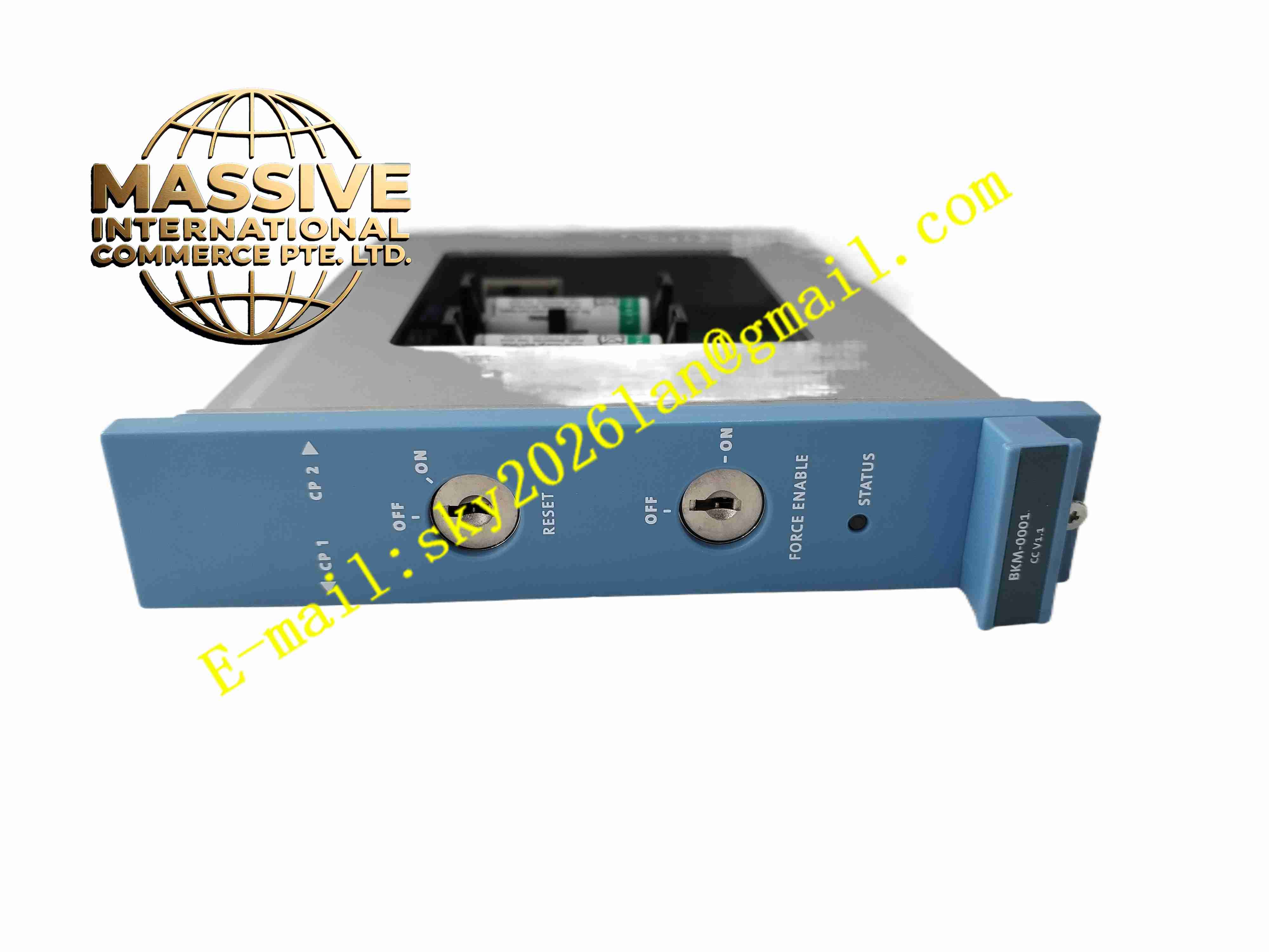
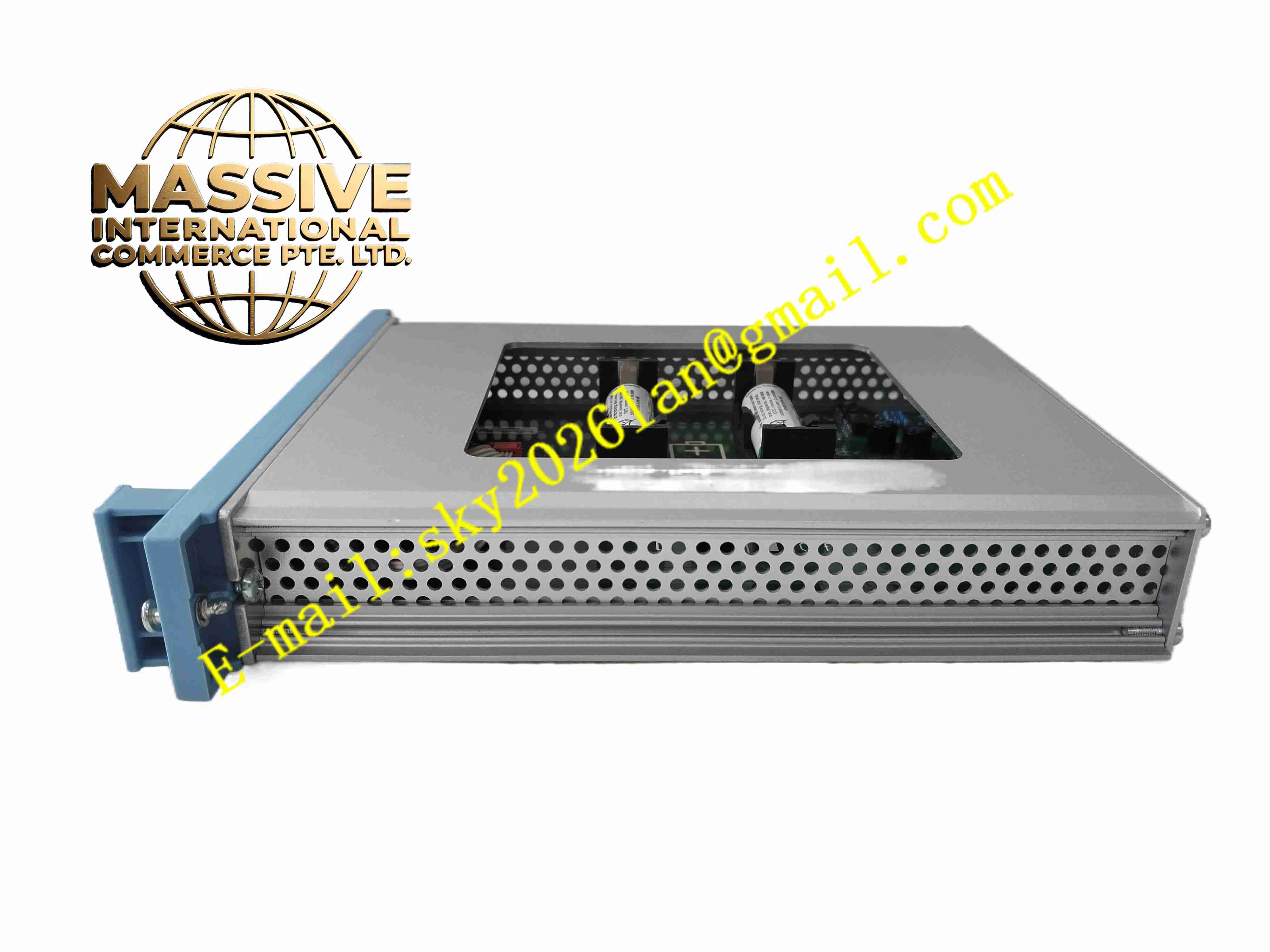
Honeywell FC-BKM-0001
Technical Specifications:
- Power Distribution: 24 VDC power distribution to all rack slots
- System Bus: High speed redundant internal safety bus
- Slot Quantity: Multiple module slots for CPU and I/O modules
- Operating Temperature: 0 °C to +60 °C
- Storage Temperature: -40 °C to +85 °C
- Relative Humidity: 5% to 95%, non-condensing
- Isolation: Isolation between power bus and signal bus
- Mounting: Cabinet panel mounting
Function Features:
- Mechanical support and positioning for all safety rack plug-in modules
- Distribute 24 VDC power supply to each module slot
- Transmit redundant internal safety bus signals between CPU and I/O modules
- Support hot swap of individual modules during system operation
- Built-in overcurrent protection for each slot power supply
- Bus termination and signal integrity maintenance for internal communication
- Slot identification for automatic module recognition by controller
- Ground bar integration for rack protective earth connection
Application Scenarios:
- Honeywell safety instrumented system rack assembly
- Oil and gas plant emergency shutdown systems
- Chemical plant SIS safety control cabinets
- Power plant boiler safety protection racks
- Refinery process safety interlock systems
Material Composition:
- Backplane Substrate: Thick multilayer FR4 fiberglass printed circuit board
- Connectors: Gold-plated female edge connectors for each module slot
- Base Frame: Painted cold rolled steel mounting frame
- Bus Components: High speed signal traces, termination resistors and surge suppression components
- Terminal Blocks: Heavy duty screw terminals for main power input and earth connection
Structural Features:
- Horizontal rack backplane board fixed inside steel cabinet frame
- Multiple gold-plated edge connector slots arranged along the board
- Separate power bus traces and high-speed signal bus traces on PCB layers
- Integrated earth bar along backplane edge
- Main power input terminal block mounted on one side of backplane
- Steel frame provides mechanical rigidity and electromagnetic shielding
Working Principle: Main 24 VDC power enters the backplane through input terminals. Backplane PCB distributes power to each module slot with independent overcurrent protection. Redundant internal safety bus traces run across the backplane. When modules are inserted into slots, gold-plated connectors connect each module to power and system bus. The backplane transmits data between CPU module and all I/O modules via high speed bus. Ground bar connects all module shields to protective earth to reduce electromagnetic interference.
Installation Requirements:
- Mount backplane steel frame firmly inside control cabinet
- Use specified torque for main power terminal screws
- Connect protective earth bar to cabinet earth point with short heavy gauge cable
- Separate backplane main power wiring from field I/O signal cables
- Keep cabinet well ventilated to maintain temperature within rated range
- Inspect gold-plated slot connectors for dust before inserting modules
Usage Notes:
- Do not plug or remove modules when power is applied unless hot swap is designed and approved
- Check tightness of main power terminals periodically
- Keep cabinet sealed to prevent dust accumulation on backplane connectors
- Avoid overloading backplane power supply beyond rated current
- Disconnect main rack power before replacing backplane
- Inspect connector gold plating for corrosion during maintenance outage







