



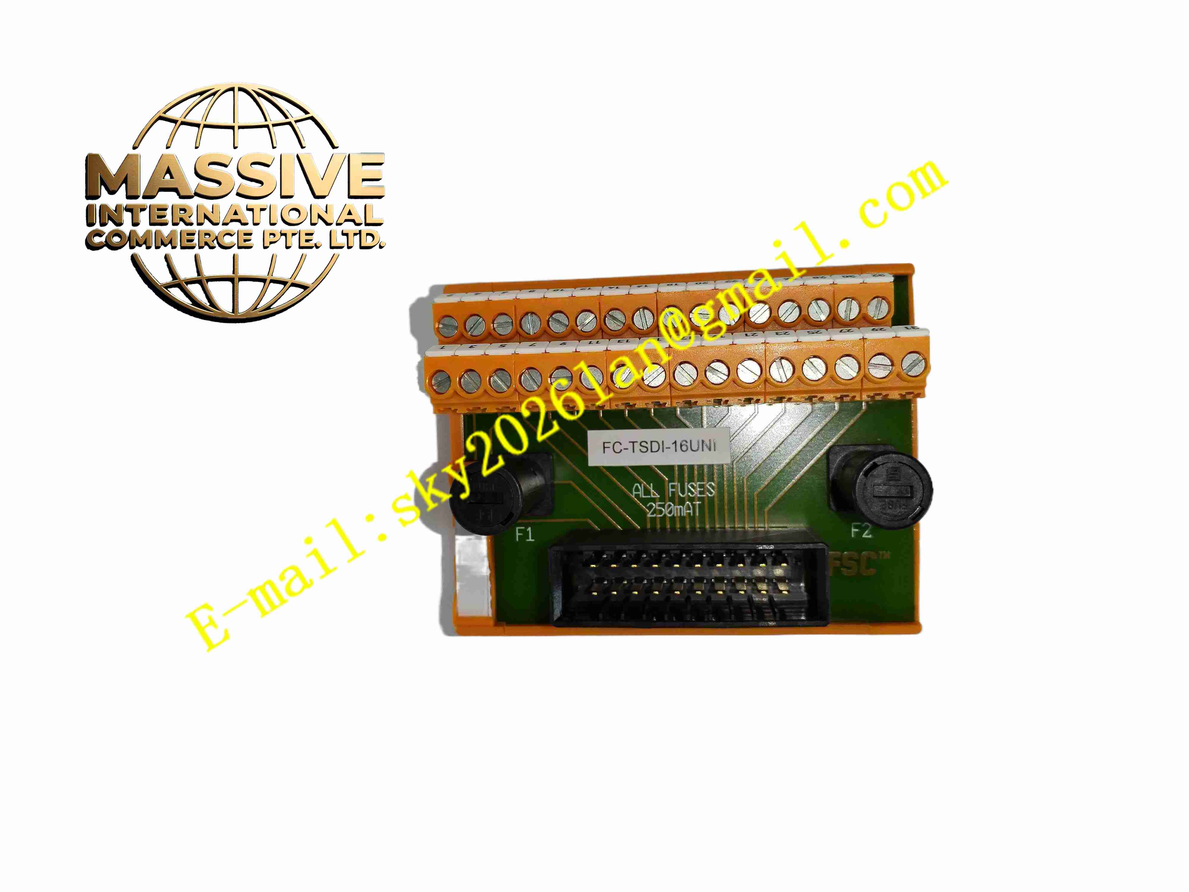
Description
Honeywell FC-TSDI-16UNI
Technical Specifications
- Product Type: Universal safety digital input field termination assembly
- Channel Count: 16 channels
- Supported Signal: Sink / source 24VDC digital input signal
- Terminal Type: Screw terminal block
- Built-in Components: Per-channel fuses, surge suppression devices, configurable signal jumpers
- Cable Interface: SIC ribbon cable connector
- Protection Rating: IP20
- Operating Temperature: -10 °C to +60 °C
- Mounting Method: DIN rail mounting
Functional Features
- 16-channel universal termination supports both sinking and sourcing 24VDC discrete input signals.
- Configurable jumper settings adapt to different field contact power supply modes.
- Per-channel fuse protection prevents fault current from spreading to rack safety module.
- Built-in surge suppression absorbs electrical transient interference on field cables.
- Dedicated SIC ribbon cable interface connects to Safety Manager safety digital input module.
- Front panel LED indicators display channel power and fault status.
- Galvanic isolation separates field wiring circuit and safety module circuit.
- Screw terminal block provides stable wiring connection for field copper conductors.
- DIN rail compact design saves cabinet installation space.
- Supports on-site channel isolation and maintenance without removing rack module.
Application Scenarios
- Safety Manager SIS universal discrete signal marshalling cabinet
- Petrochemical plant ESD mixed sink/source safety switch wiring termination
- Fire and gas detector contact signal field termination assembly
- Boiler burner management valve position feedback signal junction unit
- Offshore platform safety instrumented system mixed discrete signal wiring
Material Composition
- Housing: Flame-retardant polycarbonate plastic casing
- Terminal block: Tin-plated copper alloy screw terminals
- PCB: FR4 printed circuit board
- Protection components: Channel fuses and surge suppression diodes
- Jumper components: Configurable plastic jumpers
- Cable connector: Gold-plated copper contact pins for SIC ribbon cable
- Mounting clip: Steel DIN rail mounting bracket
Structural Characteristics
- Compact DIN rail horizontal mounting structure.
- Front screw terminals for field cable connection, front jumpers for signal configuration.
- Rear SIC ribbon cable connector links to rack safety digital input module.
- Each channel has independent fuse holder and surge suppression circuit.
- Internal isolation barrier separates field wiring side and safety module side.
- LED indicators arranged on front panel for direct visual channel status inspection.
Working Principle Field discrete safety signals connect to FC-TSDI-16UNI screw terminals. Users set configuration jumpers to select sink or source mode matching field device wiring. Signals pass through fuse and surge suppression circuit, then transmit to safety digital input module via SIC ribbon cable. Fuse breaks circuit under overcurrent fault. Surge components suppress transient voltage. Signal and fault information transfers bidirectionally between field devices and safety input module.
Installation Requirements
- Mount FC-TSDI-16UNI on standard 35mm DIN rail inside control cabinet.
- Set channel configuration jumpers according to field device sink/source requirement before power on.
- Use shielded twisted pair cable for field safety device wiring.
- Tighten terminal screws to specified torque.
- Connect SIC ribbon cable to corresponding safety digital input module.
- Separate signal cables from high power cables in cable tray.
- Complete protective earth connection for assembly housing.
- Perform continuity and channel function test after wiring completion.
Usage Notes
- Cut off field loop power before adjusting configuration jumpers or replacing fuses.
- Replace fuses with same rated specification only.
- Keep cabinet dry and free of oil mist and conductive dust.
- Check terminal tightness periodically under vibration condition.
- Do not modify internal circuit components.
- Disconnect SIC ribbon cable before insulation resistance test.
- Replace assembly immediately when permanent circuit damage occurs.







