



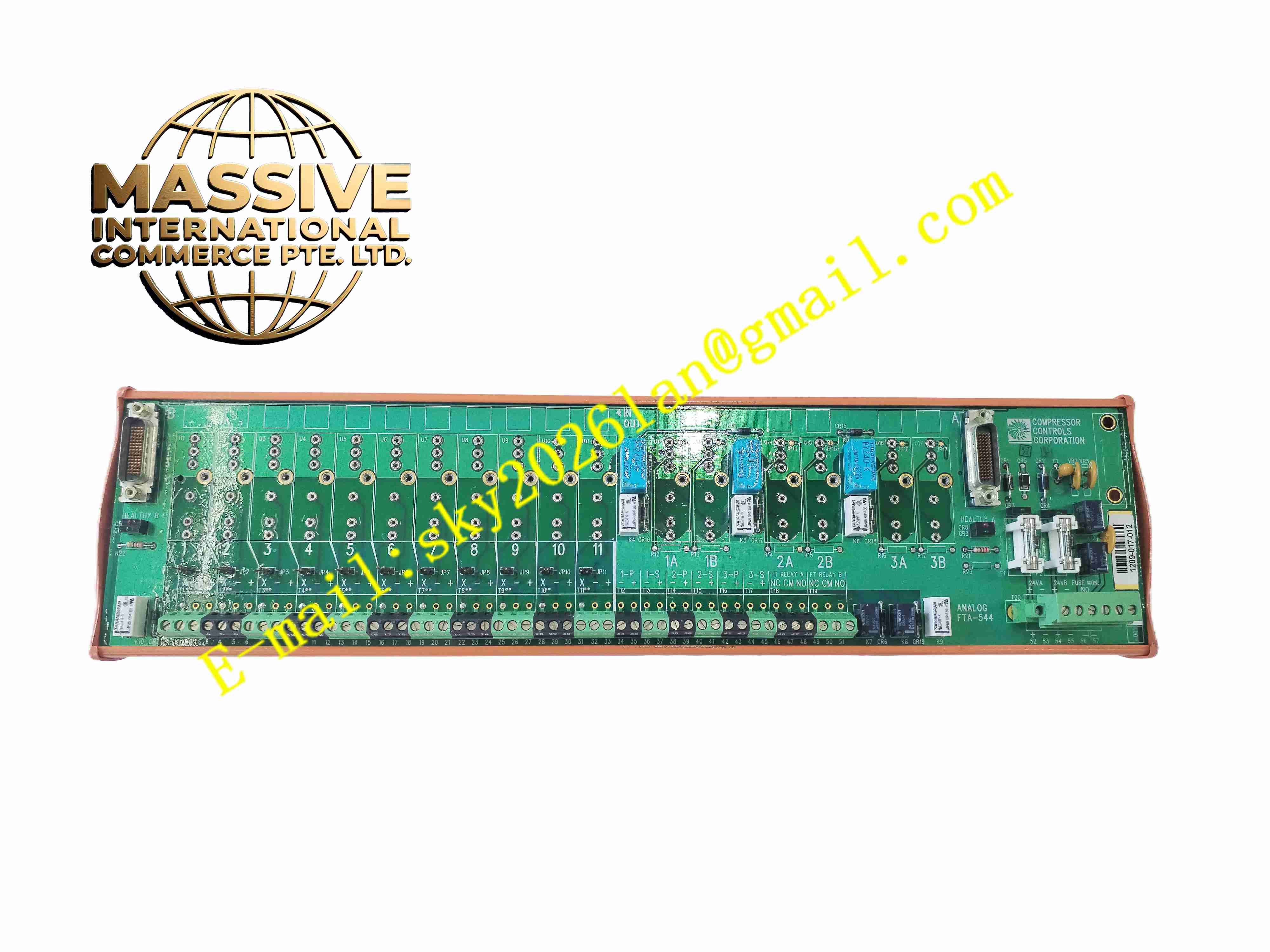
Description
Honeywell FTA-544
Technical Specifications
- Product Type: I/O field termination assembly
- Terminal Type: Screw terminal block
- Built-in Components: Per-channel fuses, surge suppression devices
- Cable Interface: Ribbon cable connector to rack I/O modules
- Protection Rating: IP20
- Operating Temperature: -10 °C to +60 °C
- Mounting Method: DIN rail mounting inside control cabinet
- Supported Signal Type: 24VDC discrete signal, 4-20mA analog signal
Functional Features
- Centralized marshalling terminal block for field instrument signal wiring.
- Independent per-channel fuse protection prevents fault current damaging rack I/O modules.
- Built-in surge suppression absorbs electrical transient voltage from field cables.
- Dedicated ribbon cable interface links termination assembly to rack I/O modules.
- Screw terminal design provides reliable connection for copper field instrument wires.
- LED indicators display channel power and fault state for on-site troubleshooting.
- Isolation barrier separates field wiring side and module ribbon cable side.
- Compact DIN rail mounting structure saves cabinet installation space.
- Supports channel isolation and maintenance without removing rack I/O modules.
- Compatible with multiple Honeywell DCS and SIS I/O modules.
Application Scenarios
- DCS and SIS system signal marshalling cabinet
- Petrochemical plant process instrument wiring termination
- Power plant boiler control signal junction assembly
- Offshore platform control cabinet instrument wiring unit
- Chemical plant safety loop signal termination
Material Composition
- Housing: Flame-retardant polycarbonate plastic casing
- Terminal block: Tin-plated copper alloy screw terminals
- PCB: FR4 printed circuit board
- Protection components: Channel fuses and transient suppression diodes
- Ribbon cable connector: Gold-plated copper contact pins
- Mounting bracket: Steel DIN rail clip
Structural Characteristics
- Compact horizontal DIN rail mounting structure.
- Front screw terminals for field instrument cable connection.
- Rear connector for ribbon cable linking to rack I/O module.
- Each signal channel has independent fuse holder and surge suppression circuit.
- Internal isolation barrier separates field transient circuit and control module circuit.
- Front panel LED indicators for direct visual channel status inspection.
Working Principle Field instrument wires connect to FTA-544 screw terminals. Signals pass through channel fuse and surge suppression circuit, then transmit to rack I/O module via ribbon cable. Fuse cuts off circuit when overcurrent occurs to protect rack I/O hardware. Surge suppression components absorb lightning induced transient voltage from field cables. Signal and fault information transmits bidirectionally between field instruments and rack I/O modules.
Installation Requirements
- Mount FTA-544 assembly on standard 35mm DIN rail inside control cabinet.
- Use shielded twisted pair cable for field instrument wiring.
- Tighten terminal screws to specified torque value.
- Connect ribbon cable to corresponding I/O module correctly.
- Separate field signal cables from high power cables in cable tray.
- Complete protective earth connection for assembly housing.
- Inspect fuse integrity and cable continuity after wiring completion.
Usage Notes
- Cut off field loop power before replacing channel fuses.
- Replace fuses with same rated specification only.
- Keep cabinet dry and free of conductive dust and corrosive gas.
- Check terminal screw tightness periodically under vibration environment.
- Do not modify internal circuit components.
- Disconnect ribbon cable before insulation resistance test.
- Replace assembly immediately when permanent circuit damage occurs.







