



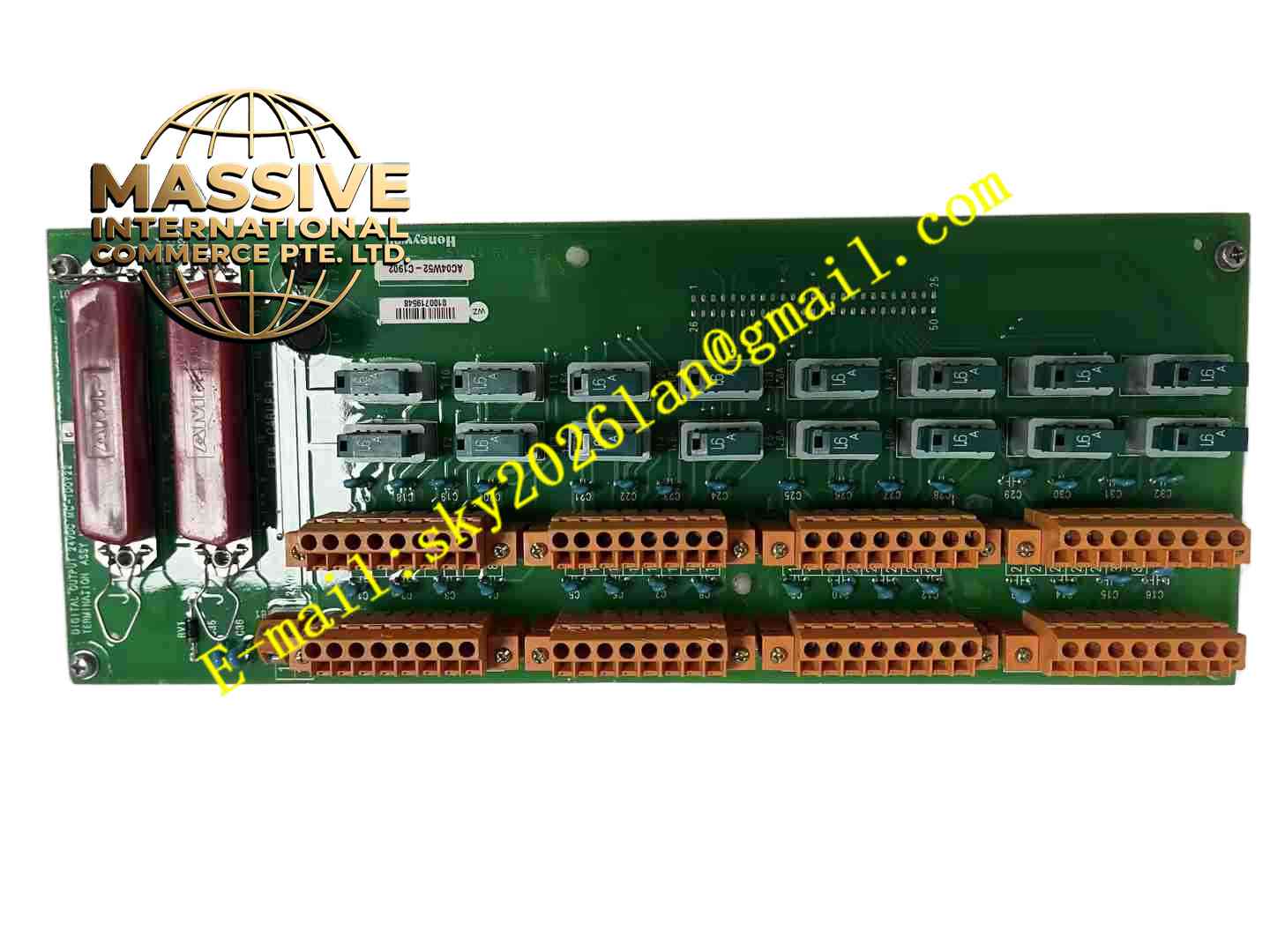
Description
Honeywell MC-TDOY22
Technical Specifications
- Brand: Honeywell
- Product Type: Field Termination Assembly for digital outputs
- Signal Type: 24 VDC digital/discrete output
- Channel Configuration: Used with 32-point digital output processors such as MC-PDOY22
- Output Style: Solid-state or relay-based output depending on the paired I/O processor
- Compatibility: Honeywell Experion PKS C200/C300 and related I/O subsystems
- Mounting: Installed in a Honeywell I/O termination rack or carrier
- Certifications: CE/CC marked versions are available depending on configuration
Functional Features
- Output wiring interface: Connects DCS digital outputs to field actuators and alarms.
- Compact termination: Reduces cabinet wiring complexity compared with conventional terminal blocks.
- LED status indication: Shows output state for easier commissioning and troubleshooting.
- High channel density: Supports up to 32 digital output channels when paired with MC-PDOY22.
- Modular maintenance: Allows replacement or inspection without rewiring the entire cabinet.
- System diagnostics: Output status is visible locally on the FTA and remotely through the DCS.
Application Scenarios
- Solenoid valve control in process systems
- Relay and contactor coil energizing
- Alarm horn and beacon control
- Pump and motor start/stop command output
- Interlock and permissive output signaling
- Chemical, oil and gas, power, water treatment, and pharmaceutical process control
Performance Parameters
- Output Voltage: Typically 24 VDC discrete output
- Channel Count: Matches the paired digital output processor, commonly 32 channels with MC-PDOY22
- Load Capability: Determined by the installed I/O processor and output type
- Response Time: Depends on the paired processor, output circuit, and field load
- Status Indication: LED indicators for output channel status
- Environmental Rating: Suitable for indoor control cabinet installation per Honeywell system specifications
Material Composition
- Assembly Body: Industrial-grade PCB with termination points
- Connectors: Mating connectors for field wiring and backplane/FTA interface
- Indicators: LEDs for output status
- Protection Components: Snubber, fuse, or isolation elements as defined by the paired I/O processor
- Mounting Hardware: Screws, guides, and carrier interfaces for secure installation
Structural Features
- FTA module design: Plugs into a Honeywell I/O termination assembly.
- Dense output terminals: Supports many output channels in a small footprint.
- Front-accessible indicators: Allows quick visual checks during operation.
- Matched processor pairing: Works with MC-PDOY22 or compatible digital output processors.
- Cabinet-friendly layout: Simplifies wiring identification and maintenance.
Working Principle
The Honeywell controller sends a digital output command to the digital output I/O processor. The processor switches the corresponding output channel, and the MC-TDOY22 routes this signal to the field device. When the output is energized, the associated LED indicates the active state. The field device, such as a solenoid valve or relay, responds to the output signal. Status information is reported back to the DCS for monitoring and alarm handling.
Installation Requirements
- Install the MC-TDOY22 in the correct termination slot for the digital output processor.
- Verify that the paired processor is the correct digital output type, such as MC-PDOY22.
- Confirm field load voltage, current, and type before wiring.
- Use appropriate fusing or external protection for inductive loads such as solenoid valves.
- Keep output wiring separated from analog and communication cables.
- Label each output channel according to the I/O database and loop drawings.
- Verify LED status after system power-up and output testing.
Precautions for Use
- Do not exceed the output voltage and current ratings of the paired I/O processor.
- Provide flywheel diodes or surge suppression for inductive loads where required.
- Do not short-circuit output terminals during testing.
- Verify field power polarity before energizing solenoid valves or relays.
- Do not remove the FTA while the system is energized unless approved procedures are followed.
- For exact output ratings, wiring diagrams, and environmental limits, refer to the official Honeywell MC-TDOY22 documentation.







