



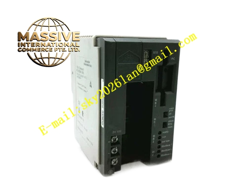
Description
Honeywell PC-E984-265
Technical Specifications
- User program memory: 8 KB
- Data memory: 4 KB
- Logic scan cycle: 5 ms per 1 KB program
- Communication interfaces: 1 RS232 programming port, 1 RS485 Modbus port
- Supported I/O module count: Up to 128 discrete points, 32 analog points
- Supply power: 24 V DC
- Operating temperature: 0 °C to +60 °C
- Program retention: Super capacitor backup, 7-day data retention after power loss
Functional Features Compatible with Modicon 984 instruction set, supports ladder logic and function block programming. RS232 programming port connects to programming computers for program upload, download and debugging. RS485 Modbus interface connects to upper HMI and SCADA systems. On-board LEDs indicate CPU run, fault and battery status. Supports online program editing and variable forced debugging. Built-in watchdog timer, automatic output reset to safe state on program runaway. Real-time clock records event timestamps.
Application Scenarios Main control for production line conveyor equipment Legacy water treatment and air compressor station PLC main control Equipment control for packaging machinery and machine tools Spare part replacement for CPU faults in existing E984 systems
Performance Parameters
- Logic scan cycle: 1 ms per 1 KB program
- Communication rate: Maximum 19200 bps
- Clock accuracy: ±2 seconds per day
- Super capacitor backup service life: 5 years
- Mean time between failures: 300,000 hours
Material Composition ABS flame retardant plastic enclosure 16-bit industrial processor chip Program storage flash memory Super capacitor backup circuit RS485/RS232 isolation chips Gold-plated backplane connector Screw wiring terminals
Structural Features Long rectangular DIN-rail mount form factor. Front panel LED array displays CPU run, fault and battery status. Side expansion interface connects to I/O racks. Bottom section houses 24 V power and communication wiring terminals. DIN rail clip for cabinet mounting.
Working Principle After power-up, the CPU loads the user control program from flash memory into RAM, entering cyclic scan mode. In each scan cycle, it reads I/O module input status, executes ladder logic computation, then writes output values to corresponding I/O modules. The RS485 interface exchanges data with upper HMI over Modbus protocol. The watchdog circuit continuously monitors program execution; if program runaway exceeds the preset cycle, the watchdog triggers reset, placing outputs in safe state. The super capacitor maintains RAM data and real-time clock during external power loss.
Installation Requirements Clip the module directly to the cabinet DIN rail. Connect 24 V DC supply with correct polarity; reversed connection damages the CPU. Connect I/O racks via expansion flat cable. Connect to programming port via computer after power-up, download matching user program. Set communication parameters to match the upper HMI.
Usage Notes Super capacitor aging causes RAM data loss after power outage; replace the capacitor every 5 years. Hot-swapping I/O expansion cabling during operation causes input/output status fluctuation and equipment misoperation. Program download interrupts current control logic; schedule downloads during equipment shutdown. Electrostatic discharge at the programming port damages the CPU communication chip; wear an anti-static wrist strap when connecting programming cables.







