



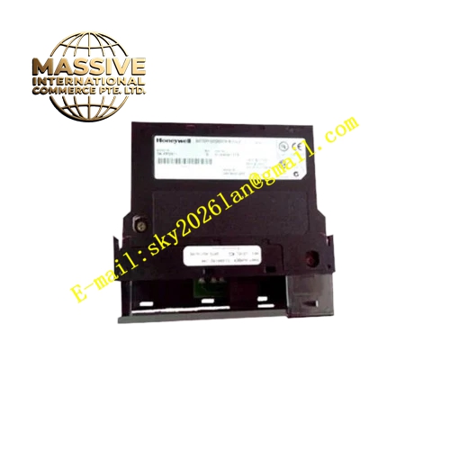
Description
Honeywell TC-IAH16I
Technical Specifications
- Channel count: 16 analog input channels
- Signal type: 4–20 mA DC current signal
- Resolution: 16-bit ADC
- Channel isolation: 2500 VAC full electrical isolation per channel
- Loop supply: 24 V DC, 20 mA per channel for two-wire transmitters
- Update cycle: 20 ms full-channel conversion
- Operating temperature: 0 °C to +60 °C
- Backplane interface: C200 I/O rack bus
Functional Features 2500 VAC isolation per channel, complete electrical separation between field side and system side. Independent 24 V DC loop supply per channel, no external transmitter power required. Per-channel wire break diagnosis, triggers channel fault alarm when transmitter circuit opens. Digital filter smooths acquisition values, suppresses field electromagnetic interference-induced signal jump. On-board LEDs indicate card power, communication and overall fault status. All acquired data frames carry CRC checksum for upload integrity. Over-range and under-range signals automatically flagged, uploaded to controller for alarm processing.
Application Scenarios Strong-interference environment transmitter signal acquisition in chemical plants High-insulation-requirement process variable measurement on offshore platforms Analog signal acquisition in explosion-adjacent cabinet installations Spare part replacement for degraded isolation performance in legacy C200 analog input cards High-precision temperature, pressure and flow signal monitoring loops
Performance Parameters
- Conversion accuracy: ±0.1% full scale
- Common mode rejection ratio: ≥90 dB
- Wire break detection response: ≤200 ms
- Temperature drift: ±25 ppm/°C
- Channel crosstalk: ≥-70 dB
Material Composition FR4 low-noise PCB substrate 16-bit ADC chip Instrumentation operational amplifier Channel isolation optocoupler array Precision metal film sampling resistors TVS surge protection diodes Gold-plated backplane edge fingers UL94 V0 flame retardant plastic front panel
Structural Features Standard Eurocard dimensions, inserts into C200 I/O rack slots. Front two rows of screw terminals silk-screened per channel number. Isolation barrier separates field signal side and backplane logic side. Independent isolation circuit per channel, no electrical connection between channels. Front panel LEDs display card run and fault status.
Working Principle Field transmitter signals connect to input terminals, on-board 24 V DC loop supply provides operating power for the transmitter. The 4–20 mA current signal passes through sampling resistor to the 16-bit ADC, converting analog value to digital data. Isolation optocouplers provide full electrical separation between field side and system side. On-board logic monitors loop impedance, identifying transmitter open circuit and short circuit faults. Converted engineering values and fault flags are packaged into communication frames, transmitted to the controller via the backplane bus.
Installation Requirements Use shielded twisted pair for transmitter cabling, single-point shield grounding. Configure signal range and engineering units per channel in software. Route analog cables separately from power cable trays, maintain ≥20 cm separation. Calibrate zero and span per channel after power-up. Maintain safe clearance between field side wiring and system side circuits.
Usage Notes Never connect AC high voltage to input terminals, high voltage destroys channel isolation optocouplers. Transmitter loop short circuit triggers card overcurrent protection; auto-recovery occurs after fault removal. Dust and moisture on the isolation surface reduce insulation performance; keep the board clean and dry. Loop load resistance exceeding rated value causes insufficient output current.







