



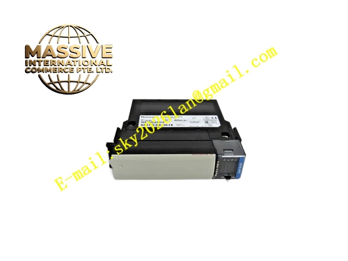
Description
Honeywell TK-IOL01
Technical Specifications
- Compatible bus: TPS I/O Link fieldbus
- Optical interface: Duplex ST fiber port
- Transmission distance: 2 km single-mode fiber
- Electrical interface: Connects to main control room I/O Link bus
- Supply power: 5 V DC from backplane
- Operating temperature: 0 °C to +60 °C
- Photoelectric conversion rate: 2 Mbps
Functional Features Bidirectional electrical-to-optical signal conversion, enables long-distance bus extension. Fiber transmission provides complete electrical isolation, blocks ground loop interference between sites. On-board signal attenuation monitoring, triggers communication fault alarm when fiber contamination or breakage occurs. On-board LEDs indicate optical transmit, optical receive and power status. Strong electromagnetic compatibility, immune to VFD and high-voltage cable radiation interference. Supports hot-swap replacement for faulty interface boards.
Application Scenarios Bus connection between main control room and remote field I/O cabinets Signal isolation transmission in strong electromagnetic interference environments Communication connection for stations with large ground potential difference Fiber retrofits for legacy copper cable systems with severe interference
Performance Parameters
- Optical transmit wavelength: 1310 nm
- Receive sensitivity: -20 dBm
- Signal conversion delay: ≤10 μs
- Fiber connector mating life: 500 cycles
- Isolation withstand voltage: Complete electrical isolation, no conductive path
Material Composition FR4 PCB substrate Optical transceiver module Level conversion chip Gold-plated ST fiber adapter Optocoupler isolation devices Metal shielded front panel
Structural Features Standard Eurocard dimensions, inserts into TPS dedicated communication slots. Front panel duplex ST fiber interface, with corresponding optical transmit and receive status LEDs. Metal shielded enclosure isolates optical circuit external interference. Board edge mounting holes lock to rack slots.
Working Principle I/O Link bus electrical signals from the main control room connect to the interface board, passing through level conversion to the optical transceiver module, which converts signals to 1310 nm optical signals transmitted over fiber to the corresponding interface board in the remote field cabinet. The remote-side board converts optical signals back to electrical signals, connecting to the field I/O cabinet I/O Link bus. Reverse data transmission follows the same path. Optical power monitoring circuit continuously measures received optical signal strength; excessive attenuation or fiber breakage triggers fault alarm.
Installation Requirements Insert fiber connectors until the clip locks into place. Maintain fiber bend radius ≥5 cm, avoid fiber breakage. Cross-connect transmit and receive fibers, local transmit connects to remote receive. Check received optical power LED after power-up, confirm signal strength is normal. Clean fiber end faces with dedicated cleaning pen when contaminated.
Usage Notes Never look directly into the lit fiber end face; strong laser causes eye injury. Excessively tight fiber bend radius causes fiber breakage and increased optical attenuation. Oil and dust on fiber connectors cause communication packet loss; clean end faces regularly. Route fiber cables separately from high-power cable trays, prevent rodent damage.







