Description
ICS Triplex T3420A
Technical Specifications & Performance Parameters:
- Power Supply: 20 V DC ~ 32 V DC backplane power feeding, nominal 24 V DC
- Channel Configuration: 16 single‑ended channels or 8 differential channels, jumper configurable
- Selectable Signal Ranges: 0‑5 V, 0‑10 V, ±5 V, ±10 V
- Conversion Resolution: 16‑bit ADC per redundant channel
- Basic Measurement Accuracy: ±0.05 % full scale
- Temperature Drift: 55 ppm/°C
- Common‑Mode Rejection Ratio: 140 dB
- Galvanic Isolation Rating: 2500 V between field side and internal safety bus
- Data Update Rate: 3.60 ms for single‑ended mode, 1.80 ms for differential mode
- Continuous Over‑Voltage Protection: ±30 V channel‑level surge withstand
- Operating Temperature: ‑20 °C ~ +60 °C
- Storage Temperature: ‑40 °C ~ +85 °C
- Ambient Humidity: 0 %‑95 % RH non‑condensing
- Safety Certification: TÜV IEC 61508 SIL 3
- Maximum Power Consumption: 2.2 W
- Weight: 1.18 kg
- Form Factor: Standard Regent‑Plus rack plug‑in module
Functional Features:
- Independent triple analog‑to‑digital conversion circuit for every input channel, complete 2oo3 hardware voting inside module
- Jumper‑based signal range switching, no firmware reconfiguration required for range modification
- Continuous channel‑level diagnostics, detect over‑voltage condition, wiring fault and internal circuit anomaly
- Hot‑swap support, online module replacement without safety system shutdown or logic interruption
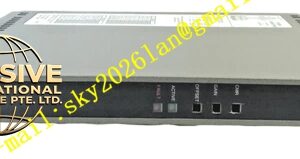
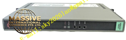
- Front‑panel multi‑LED indicator array, show module running status, channel fault status and TMR health status
- Complete surge protection against field mis‑wiring and transient voltage surges
- High‑performance noise suppression for heavy electromagnetic‑interference industrial environment
- Fault events carry precise timestamps and upload to system fault historian
- Electrical isolation blocks field‑side disturbance from penetrating safety domain backplane bus
Working Principle: Each field voltage signal feeds into three independent sampling and A/D conversion sub‑circuits simultaneously. Three groups of converted digital values go through hardware 2‑out‑of‑3 voting circuit to output final validated measurement value. On‑board diagnostic circuit monitors channel voltage amplitude continuously. When over‑voltage, abnormal impedance or internal hardware deviation occurs, the module generates fault flag and isolates the faulty sub‑channel. Valid digital measurement data transfers to Regent‑Plus processor module via rack internal backplane bus. Single sub‑channel hardware failure cannot corrupt final channel output result.
Material Composition & Structural Characteristics:
- Outer housing: High‑strength die‑cast aluminum alloy shell with anti‑corrosion matte coating, provide electromagnetic shielding
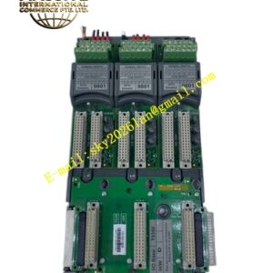
- Internal circuit substrate: Multi‑layer FR‑4 high‑temperature industrial printed circuit board, adopt high‑reliability wave‑soldering assembly
- Backplane connector: Gold‑plated high‑density anti‑vibration industrial connector, resist oxidation under long‑term cabinet operation
- Front panel: Flame‑retardant PC engineering plastic, embed LED indicator window and module specification label area
- Overall card‑type plug‑in construction, protection grade IP20, designed for horizontal slot installation inside Regent‑Plus control rack
Installation Requirements:
- Insert module into designated analog‑input slot of Regent‑Plus series rack chassis, tighten front‑panel locking screws
- Set signal‑range jumpers on module side according to actual field sensor output type before power‑on operation
- Field signal cables use shielded twisted‑pair cables, keep physical separation from high‑voltage power cables, maintain minimum 15 cm spacing
- Cable shielding layer implements single‑end grounding at cabinet protective ground bus‑bar
- Cabinet protective ground resistance stays below 4 Ω
- Control cabinet maintains smooth air convection for heat dissipation, avoid local hot‑spot accumulation
- Do not install in location with heavy salt‑fog, corrosive gas or continuous mechanical shock
Application Scenarios:
- Voltage‑type process parameter acquisition for petrochemical ESD emergency shutdown systems
- Turbine and compressor auxiliary process safety monitoring
- Tank level, draft pressure and reactor safety‑related voltage signal measurement
- Fire‑gas safety monitoring system analog sensor signal collection
- Safety instrumented system for chemical fine‑chemical production facilities
Usage Notes:
- Execute hot‑swap operation only when system reports full module health status
- Module shell disassembly is forbidden; zero user‑serviceable internal components
- Strictly match jumper setting with actual field signal range; wrong jumper setting triggers measurement deviation and channel fault
- Prevent field over‑voltage signal from directly accessing channel terminals
- After module replacement, complete channel accuracy calibration and fault‑response verification before formal online operation
- Operate strictly within defined operating temperature range
- Periodically inspect field cable insulation and terminal fastening torque