Description
ICS Triplex T8312-4
Technical Specifications
- Model Variant: T8312-4 supporting up to 4 expander chassis
- Alternative Variant: T8312-7 supporting up to 7 expander chassis
- Communication Protocols: ModBus TCP/IP, ModBus RTU serial
- Operating Temperature: Minus 40 degrees Celsius to plus 70 degrees Celsius
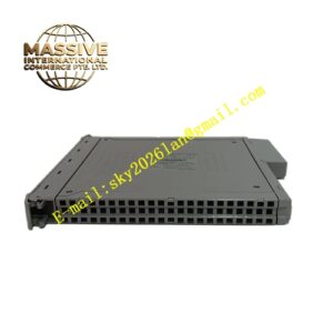
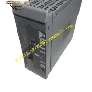
- Dimensions: 133 millimeters by 133 millimeters by 63 millimeters
- Weight: 0.65 kilograms
- Function: Connects Expander Interface Modules in the controller chassis to Processor Interface Modules in expander chassis
Functional Features
- DIP switch setup for chassis ID configuration
- Controller chassis ID set to number 1
- Expander chassis IDs set from 2 to 8 for the first set of seven
- Support for additional chassis using second adapter with IDs 9 to 15
- Fault-tolerant communication maintaining TMR integrity
- Compact design for control cabinet installation
Application Scenarios
- Systems requiring up to 4 expansion chassis
- Distributed I/O in medium-scale safety systems
- Oil and gas processing with moderate I/O expansion needs
- Chemical plant safety instrumented systems
- Power generation distributed control
Performance Parameters
- Supports 4 expander chassis per adapter
- Maintains TMR data integrity across expansion bus
- Deterministic communication timing
Material Composition and Structure
- Industrial-grade steel and aluminum construction
- DIP switch configuration panel
- High-density connectors for expansion bus
- Compact form factor
Working Principle The adapter unit sits between the controller chassis and expansion chassis, routing triplicated data signals between Expander Interface Modules and Processor Interface Modules. DIP switches configure the chassis ID for each connected rack, ensuring proper addressing in the TMR network.
Installation Requirements
- Install in control cabinet with adequate clearance
- Configure DIP switches before energizing
- Connect using specified expansion bus cables
- Ensure proper grounding
Operating Precautions
- Verify DIP switch settings match chassis configuration
- Do not change switch settings while powered
- Monitor communication integrity across expansion links