Description
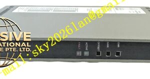
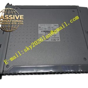
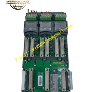
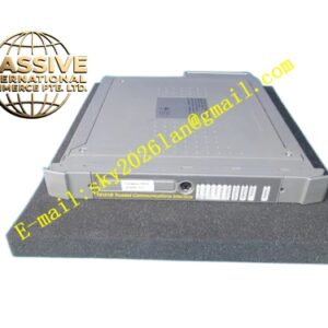
ICS Triplex T3484
Technical Specifications & Performance Parameters:
- Power Supply: 20 V DC ~ 32 V DC backplane power supply, nominal 24 V DC
- Channel Count: 16 analog output channels
- Output Signal Ranges: 0‑20 mA, 4‑20 mA
- Output Basic Accuracy: ±0.12 % full scale
- Per‑Channel Load Impedance: 0‑600 Ω
- Loop Diagnostics: Detect field cable open‑circuit and short‑circuit
- Operating Temperature: ‑40 °C ~ +70 °C
- Storage Temperature: ‑40 °C ~ +85 °C
- Safety Certification: TÜV IEC 61508 SIL 3
- Maximum Power Consumption: 24 W
- Weight: 1.22 kg
- Form Factor: Standard Regent‑Plus rack plug‑in module
Functional Features:
- Per‑channel triple‑redundant D/A conversion and drive circuit, hardware 2‑out‑of‑3 voting mechanism
- High‑channel‑density design, maximize cabinet‑slot utilization efficiency
- Channel‑level loop diagnostics for open‑circuit and short‑circuit fault identification
- Hot‑swap support for online module replacement
- Software configurable fail‑safe output value under fault condition
- Front‑panel LED array indicates channel status, module running status and fault‑alarm information
- Timestamped channel‑level fault‑data upload to system fault historian
- Galvanic isolation separates field‑output loop and internal safety backplane bus
Working Principle: Digital control commands transmit from safety processor to T3484 via rack backplane bus. Every analog‑output channel owns three independent D/A conversion sub‑circuits, generate analog current output synchronously. Hardware voting circuit selects valid output value to drive field instrument loop. Diagnostic circuit continuously monitors loop impedance and current value. When open‑circuit or short‑circuit fault occurs, module triggers timestamped fault alarm and executes pre‑configured fail‑safe output state. Single sub‑circuit hardware failure gets isolated automatically and does not affect channel output performance.
Material Composition & Structural Characteristics:
- Housing: Die‑cast aluminum alloy electromagnetic‑shielding shell
- Circuit board: Multi‑layer FR‑4 high‑density industrial printed circuit board, integrate multi‑group D/A conversion and drive components
- Connectors: Gold‑plated backplane connector and high‑density field‑wiring terminal block
- Front panel: Flame‑retardant engineering plastic with LED indicator window, IP20 protection grade
- Card‑type plug‑in structure for Regent‑Plus rack‑slot installation
Installation Requirements:
- Insert module into high‑density analog‑output slot of Regent‑Plus rack chassis, tighten front‑panel locking screws
- Field analog‑output cables use shielded twisted‑pair cables, maintain safe separation distance from high‑voltage power cables
- Cable shielding layer single‑end connects to cabinet ground bus‑bar
- Cabinet protective ground resistance ≤4 Ω
- Ensure sufficient cabinet air convection for heat dissipation due to high‑channel‑density power consumption
- Field actuator loop load impedance must comply with module rated load‑impedance specification
Application Scenarios:
- Large‑point‑count analog‑adjustment output for petrochemical safety‑instrumented‑systems
- Cabinet‑space‑limited safety‑control‑system analog‑loop expansion
- Chemical‑plant multi‑loop safety‑interlock analog‑actuator control
- Power‑plant auxiliary workshop multi‑channel safety‑related analog‑output
- LNG plant multi‑valve safety‑control analog‑signal output
Usage Notes:
- Hot‑swap operation only allowed under normal system health status
- Do not disassemble module outer shell; no field‑serviceable internal components
- Pay attention to overall heat dissipation condition caused by high‑channel‑density power consumption
- Prevent field‑side output‑loop short‑circuit damage
- After module replacement, complete channel‑accuracy calibration and fault‑detection‑function verification
- Operate strictly within rated operating temperature range
- Periodically inspect field‑cable insulation condition and terminal‑tightening torque