Description
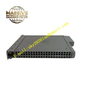
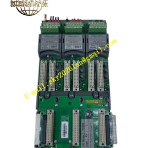
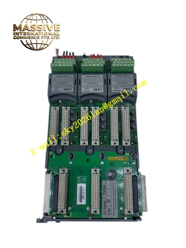
ICS Triplex T8311
Technical Specifications
- Voltage Range: 20 to 32 VDC
- Maximum Load and Heat Dissipation: 40 Watts
- Expander Bus Data Rate: 250 Mbps
- Maximum Communication Distance: 30 meters with TC-301 copper cable, up to 10 kilometers using fiber converters
- Module Clock Speed: 50 MHz
- Compatible Chassis: T8300 expansion chassis
- Operating Temperature: Minus 5 degrees Celsius to plus 60 degrees Celsius
- Non-Operating Temperature: Minus 25 degrees Celsius to plus 70 degrees Celsius
- Operating Humidity: 5 to 95 percent relative humidity
- Dimensions: 266 millimeters height by 31 millimeters width by 303 millimeters depth
- Weight: 1.14 kilograms
Functional Features
- HIFT TMR architecture with comprehensive diagnostics
- Dual redundant plus 24 VDC power inputs from controller chassis
- Automatic selection of active module by TMR processor
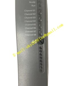
- LED status indicators showing Healthy, Active, and Standby states
- Fault-tolerant communication preventing single-point failures
- Rapid fault identification through built-in diagnostics
Application Scenarios
- Controller-to-expander chassis interconnection
- Distributed safety systems requiring multiple I/O racks
- Oil and gas processing with geographically separated I/O
- Chemical plant safety instrumented systems
- Power generation distributed control
Performance Parameters
- 250 Mbps data rate ensuring high-speed deterministic communication
- Up to 7 expander chassis supported per interface
- 30 meter copper cable distance or 10 kilometer fiber distance
- Continuous operation during single path failure through TMR voting
Material Composition and Structure
- Industrial-grade aluminum and steel construction
- Conformal coated circuit boards
- High-density connectors for expansion bus
- Front panel LEDs for status indication
- Single-width module form factor
Working Principle The T8311 installs in single-width slots in the controller chassis, with dual modules placed in left-hand odd-numbered slots. The TMR processor automatically selects the active module. It manages communication between the controller chassis backplane and expansion chassis processors via the 250 Mbps expander bus, maintaining data integrity through triplicated paths and voting logic.
Installation Requirements
- Install in controller chassis slots only
- Use TC-301 copper cable or fiber converters for expansion bus
- Configure dual modules in left-hand odd-numbered slots
- Ensure redundant power connections from controller chassis
- Verify T8300 chassis compatibility
Operating Precautions
- Monitor Healthy LED for green steady indication, red flashing indicates fault
- Verify Active LED shows green steady when module is primary
- Check Standby LED shows green steady in standby mode
- Replace faulted modules showing persistent red indicators
- Maintain cable connections to prevent communication interruptions