Description
ICS Triplex T8461
Technical Specifications:
- Channel Count: 40 TMR input or output channels per module (depending on variant)
- Signal Type: 24 V DC digital (sourcing high-side for output variant)
- Power Supply: Logic power via Trusted backplane; field supply typically 24 V DC
- Operating Temperature: 0°C to 60°C (non-condensing humidity)
- Isolation: 2500 V DC optical isolation
- Dimensions: Standard single-width Trusted I/O module
- Weight: Approximately 0.6–0.8 kg
- Safety Certification: IEC 61508 SIL 3 (system level)
- Communication: Trusted TMR backplane interface to the controller
Functional Features:
- 40 TMR channels providing high-density field interfacing
- Per-channel fault reporting and health status diagnostics
- Hot replacement capability allowing online module swap in a powered rack
- Field power segregation with separate field power feeds for output groups
- EMC-hardened design for improved noise immunity and long-term stability
- Backplane-powered logic requiring no extra logic supply wiring
- Compatible with standard Trusted field termination assemblies (FTAs)
- On-board Sequence of Events (SOE) reporting with 1 ms resolution (output variant)
- Automatic line monitoring for open circuit and short circuit detection
- Stuck-on and stuck-off fault detection
Application Scenarios:
- Emergency shutdown (ESD) and process shutdown (PSD) in oil and gas, petrochemical, and refining
- Boiler/burner management, fuel skids, and combustion safety
- Turbomachinery and compressor anti-surge systems
- High-availability discrete control in pharmaceuticals and specialty chemicals
- Utilities and power plants for balance-of-plant interlocks and permissives
- Fire and gas detection system signal processing
Performance Parameters:
- Channel Density: 40 channels per module
- Diagnostic Coverage: Per-channel voltage, current, and fault status monitoring
- Fault Tolerance: First fault — fault tolerant; Second fault — fail-safe
- SOE Resolution: 1 ms (output variant)
- Isolation: 2500 V DC optical isolation between field and logic
Material Composition:
- Multi-layer industrial PCB with conformal coating
- High-reliability optocoupler isolation barriers
- Precision-machined aluminum chassis
- Gold-plated backplane connector pins
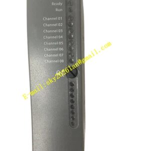
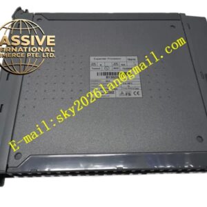
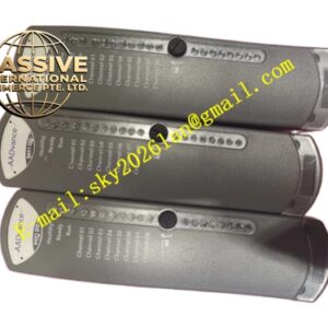
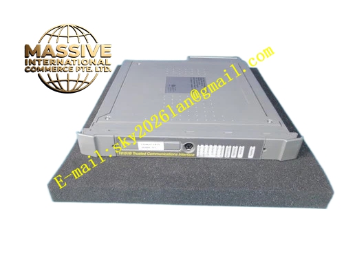
Structural Features: The module is a standard single-width Trusted I/O module that plugs into any available I/O slot in a Trusted processor or expander chassis. Mechanical keying prevents insertion into an incorrect slot. The front panel features individual channel status LEDs and module-level fault/health indicators. Field connections are made through removable field termination assemblies (FTAs).
Working Principle: For the input variant, each of the 40 channels receives field signals through three independent TMR signal paths. The module performs comprehensive diagnostic testing including current measurement and voltage voting on each portion of the output channels. For the output variant, each triplicated section (slice) of the module receives output data from the Trusted TMR processor and sends its data to an internal safety layer hardware voter. Each slice uses the voted data to control the outputs through a six-element voted output array.
Installation Requirements:
- Install in a Trusted I/O chassis within a clean, ventilated cabinet
- Maintain adequate spacing for airflow and service access
- Use recommended field termination assemblies and follow 24 V DC segregation practices
- Use ferrules and proper labeling on all field wiring
- Keep digital output wiring separated from VFD and high-current cables
- Bond cable shields at a single approved grounding point
Usage Precautions:
- De-energize loads before making wiring changes
- Verify permissives and bypasses during hot-swap operations
- Follow site Management of Change (MOC) and Lockout/Tagout (LoTo) procedures
- Perform periodic channel proof testing and inspect terminal tightness
- Remove dust with dry air during routine maintenance
- Keep at least one spare module per panel stored in anti-static packaging