Description
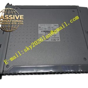
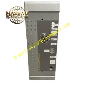
ICS Triplex T8403CX
Technical Specifications
| Parameter | Specification |
|---|---|
| Product Model | T8403CX |
| Manufacturer | ICS Triplex / Schneider Electric |
| System Platform | Triconex Tricon (V10 and V11 controller generations) |
| Module Type | TMR analog input module |
| Input Channels | 8 independent channels |
| Signal Types | 4–20 mA (standard), with optional support for 0–20 mA or 1–5 V |
| Input Impedance | Approximately 250 Ω (for 4–20 mA) |
| Resolution | 16-bit A/D conversion per lane |
| Redundancy Architecture | 2oo3 voting with automatic fault masking |
| Isolation | Channel-to-channel and channel-to-system isolation (typically over 500 V DC) |
| Diagnostic Coverage | Continuous wire-break, short-circuit, signal drift, and cross-channel comparison |
| SIL Certification | SIL 3 (IEC 61508 and IEC 61511, TÜV-certified) |
| Operating Temperature | -20°C to +60°C |
| Storage Temperature | -40°C to +85°C |
| Dimensions | 200 mm × 150 mm × 50 mm |
| Weight | 2 kg |
| Lifecycle Status | Discontinued (Obsolete) |
Functional Features
- Triple Modular Redundancy: Three independent signal paths for each input channel ensure continuous operation even if one channel fails
- High-Resolution Conversion: 16-bit A/D conversion per lane provides precise measurement of process variables
- Comprehensive Diagnostics: Continuous monitoring detects wire-break, short-circuit, signal drift, and cross-channel discrepancies
- Galvanic Isolation: Channel-to-channel and channel-to-system isolation protects against destructive field loop faults
- Automatic Fault Masking: The 2oo3 voter automatically excludes a faulty channel from the output calculation
- Front-Panel Status LEDs: Channel status, module OK, and fault indication visible on the front panel
Application Scenarios
- Safety instrumented systems in oil & gas refineries
- Chemical process pressure and temperature monitoring
- Flow measurement in pipeline safety loops
- Level monitoring in storage tank safety systems
- Critical analog variable acquisition in power plants
Performance Parameters
- Measurement Accuracy: High-precision 16-bit resolution ensures accurate process variable acquisition
- Signal Integrity: Isolation barriers prevent ground loop interference
- Fault Response: Automatic fault detection and channel exclusion within milliseconds
- Safety Integrity: Maintains SIL 3 performance even with one failed channel
Material Composition
- Enclosure: Industrial-grade metal housing with protective finish
- Circuit Board: Multilayer PCB with conformal coating
- Connectors: High-reliability backplane and field terminal connectors
- Components: Industrial-grade precision resistors and A/D converters
Structural Characteristics
- Standard Tricon Module Form Factor: Compatible with Tricon I/O chassis
- Front-Panel Labeling: Clearly marked “T8403CX” with revision code
- LED Indicators: Status LEDs for each channel and module health
- Backplane Interface: Proprietary Tricon high-integrity TMR bus connection
Working Principle
Each of the eight analog input channels is connected to three independent A/D conversion circuits. All three circuits simultaneously sample the incoming 4–20 mA signal. The 2oo3 voter compares the three converted values and outputs the median value to the safety controller. If one A/D circuit drifts or fails, the voter detects the discrepancy and masks that channel while continuing to output the correct value from the remaining two channels.
Installation Requirements
- Install in a compatible Tricon I/O chassis slot
- Use shielded twisted-pair cables for field connections
- Ensure proper grounding of cable shields at one end only
- Verify termination resistor configuration for current loop signals
- Maintain environmental conditions within specified ranges
Operating Precautions
- This module is obsolete; verify authenticity and calibration when sourcing from secondary markets
- Monitor channel status LEDs for drift or fault indication
- Perform periodic proof testing to verify SIL integrity
- Replace failed modules promptly to restore full TMR redundancy
- Follow proper ESD handling procedures during installation