Description
ICS Triplex T9451
Technical Specifications:
- Output Channels: 8 independent digital output channels
- Output Current: 1 A continuous per channel
- Maximum Load Voltage: 32 V DC
- Power Supply: 24 V DC (dual redundant power input)
- Operating Temperature: -40°C to +85°C
- Dimensions: 3.5 × 19.8 × 17.1 cm
- Weight: 0.56 kg
- Safety Certification: IEC 61508 SIL 3, CE
- Protection Features: Per-channel voltage/current monitoring, reverse current protection, short circuit and open circuit detection
Functional Features:
- Triple Modular Redundancy (TMR) architecture maintaining normal operation under single-point faults
- Full per-channel diagnostics including voltage monitoring, load current monitoring, reverse current protection, and short circuit/open circuit detection
- Hot-swappable design allowing module replacement during live system operation
- Automatic line monitoring for field wiring fault detection
- Stuck-on and stuck-off fault detection for output switching elements
- Dual redundant field power supply without the need for external diodes
- Output module isolates the processor from potential faults in the output control circuit and field connections
Application Scenarios:
- Emergency shutdown valve actuation
- Safety interlock relay driving
- Fire and gas system alarm output
- Process shutdown signal distribution
- Turbine trip solenoid control
- Critical pump and compressor start/stop commands
Performance Parameters:
- Continuous Output Current: 1 A per channel
- Maximum Switching Voltage: 32 V DC
- Fault Detection: Stuck-on, stuck-off, short circuit, open circuit
- Safety Integrity Level: SIL 3 per IEC 61508
- Response Time: Designed for immediate output shutdown when required
Material Composition:
- Industrial-grade PCB with high-reliability output switching components
- Optocoupler isolation between processor logic and output channels
- Robust metal chassis with rack-mount provisions
- Gold-plated output terminal contacts
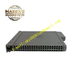
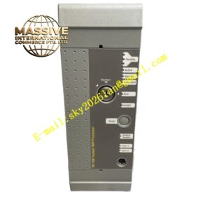
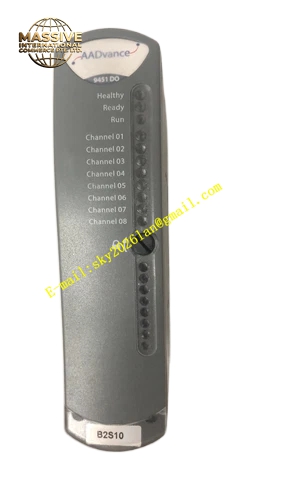
Structural Features: The module is designed for AADvance system rack mounting. Each of the 8 output channels has an individual status LED on the front panel. The module includes internal isolation between the processor section and the output channel control/data management circuits, protecting the processor from field-side faults.
Working Principle: The TMR architecture processes each output command through three independent channels. A hardware voter determines the correct output state based on majority agreement. Each output channel incorporates a six-element voted array for the output switch, providing fault-tolerant uninterrupted control even under an output switch failure condition. When a channel load exceeds safe limits, the output channel protection activates automatically. The reverse voltage protection circuit on each output channel ensures that externally applied voltages do not produce current flowing back into the module output.
Installation Requirements:
- Install in an AADvance system rack with proper backplane connection
- Ensure dual redundant 24 V DC power supply is connected
- Use appropriately rated field wiring for the 1 A per channel output capacity
- Verify load voltage does not exceed 32 V DC
Usage Precautions:
- Verify all channel diagnostics are functioning before placing the system in service
- Monitor for short circuit and open circuit alarms during operation
- Use hot-swap procedures when replacing modules in a live system
- Do not exceed the 1 A continuous current rating per channel
- Ensure proper grounding of the rack and field wiring
- Perform periodic proof testing of output channels as part of the safety system maintenance program