Description
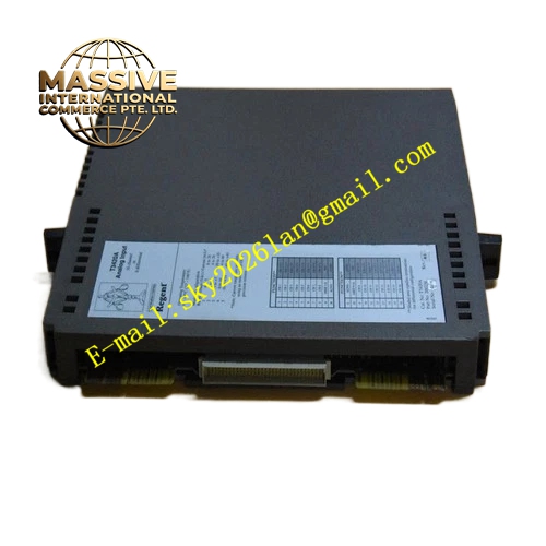
ICS Triplex T8473
Technical Specifications & Performance Parameters:
- Output Signal Type: Isolated 120 VAC digital output
- Channel Quantity: 8 TMR‑voted output channels
- Field Supply Voltage Range: 90 VAC ~ 132 VAC
- Per‑Channel Resistive Load Current: Max 1 A
- Per‑Channel Inductive Load Rating: 50 VA at 120 VAC
- Galvanic Isolation Rating: 2000 V reinforced isolation between backplane‑side and each field‑output channel
- Backplane Power Supply: 20‑32 VDC, nominal 24 VDC from Trusted rack backplane
- Module Power Consumption: Max 7.8 W
- Protection Mechanisms: Per‑channel over‑current protection, short‑circuit current‑limiting, over‑temperature protection
- Safety Certification: TÜV IEC 61508 SIL 3, UL, CE
- Operating Temperature: ‑20 °C ~ +60 °C
- Storage Temperature: ‑40 °C ~ +85 °C
- Ambient Humidity: 5 %‑95 % RH non‑condensing
- Weight: 1.15 kg
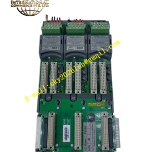
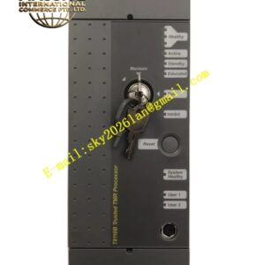
- Form Factor: Standard Trusted rack plug‑in module
Functional Features:
- Full TMR triple‑modular redundant internal architecture for each output channel, hardware 2‑out‑of‑3 voting mechanism
- 8‑channel isolated 120 VAC digital output for safety‑critical AC‑type field actuators
- Hot‑swap support for online module replacement without safety‑system logic interruption
- Comprehensive channel‑level diagnostics, detect output‑channel short‑circuit, over‑load, internal circuit fault and field‑loop abnormal state
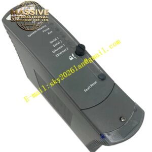
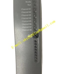
- Front‑panel multi‑LED indicator array, display module overall health status, each channel drive‑state and fault‑alarm status
- Timestamped channel‑fault events upload to system fault historian via IMB backplane bus
- Reinforced galvanic‑isolation design, block high‑voltage field‑side interference from invading Trusted backplane bus
- Cooperate with matched FTA field‑termination‑assembly to complete field‑cable wiring transition and secondary surge‑protection
Working Principle: Trusted processor module sends safety‑output logic commands to T8473 through IMB backplane bus. Three independent internal TMR slices receive identical drive‑commands simultaneously. Each slice generates independent drive‑signal, and hardware voting‑circuit executes 2‑out‑of‑3 voting to confirm final valid output state. Valid drive‑signal passes reinforced isolation circuit, then transmits to matched FTA termination assembly and field‑side 120 VAC actuators. On‑board monitoring circuit continuously samples each channel output‑current and internal circuit temperature. When channel over‑current or internal fault occurs, module locks corresponding faulty channel, generates timestamped fault‑alarm and uploads fault information to main system. Single‑slice internal fault will not affect normal output function of whole module.
Material Composition & Structural Characteristics:
- Housing: Die‑cast aluminum alloy shielding shell, realize electromagnetic shielding and auxiliary heat dissipation
- Circuit substrate: Multi‑layer FR‑4 high‑voltage‑resistant industrial printed circuit board, integrate TMR signal‑processing, isolation and power‑drive semiconductor components
- Backplane connector: Gold‑plated high‑density anti‑vibration industrial connector
- Front panel: Flame‑retardant PC engineering plastic, embed LED indicator window, protection grade IP20
- Plug‑in card‑type structure for Trusted rack dedicated I/O‑slot installation
Installation Requirements:
- Insert T8473 module into dedicated I/O slot of Trusted main or expander rack chassis, fully tighten front‑panel locking screws
- Connect T8473 with matched FTA field‑termination‑assembly by using factory‑specified dedicated ribbon‑cable
- Field‑side 120 VAC actuator wiring must use high‑voltage‑rated shielded cables, strictly separate routing from low‑voltage instrument cables
- Cable shielding layer single‑end grounding at cabinet protective ground bus‑bar
- Cabinet protective ground resistance ≤4 Ω
- Calculate total field‑actuator load‑capacity strictly, ensure each channel load does not exceed rated electrical‑specification limit
- Keep installation location away from corrosive‑gas and continuous strong‑vibration environment
Application Scenarios:
- Petrochemical ESD safety‑system 120 VAC safety‑solenoid‑valve driving control
- Chemical plant safety‑interlock AC‑type safety‑actuator output control
- Fire‑gas suppression system high‑voltage AC‑actuator safety‑control‑signal output
- Off‑shore oil‑gas platform Trusted safety‑instrumented‑system AC‑safety‑valve drive‑module
- Power‑plant safety‑shutdown system 120 VAC safety‑relay control output
Usage Notes:
- Hot‑swap operation is permitted only when Trusted main system reports full hardware‑health status
- Module shell disassembly is forbidden; internal high‑voltage circuit exists, zero user‑serviceable internal components
- Do not use non‑standard ribbon‑cables to connect with matched FTA termination‑assembly
- After module replacement, verify each channel output‑drive function and channel‑fault‑diagnostic response performance
- Operate strictly within rated operating temperature and field‑load‑capacity specification limits
- Periodically inspect high‑voltage field‑wiring terminal fastening torque and cable‑insulation performance