Description
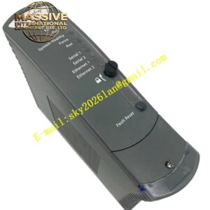
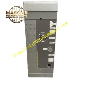
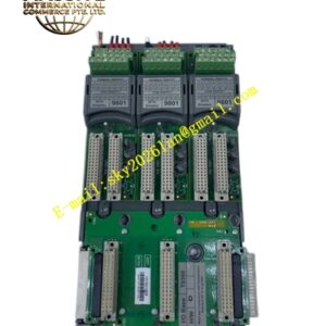
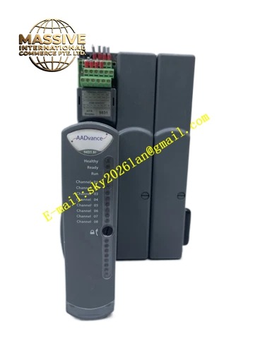
ICS Triplex T8870
Technical Specifications & Performance Parameters:
- Supported Field Supply Voltage: 90 VDC ~ 140 VDC
- Channel Quantity: 32 digital output channels
- Power‑Group Isolation Rating: 250 V basic fault isolation; 150 V continuous reinforced isolation between power groups
- Power‑Group To‑Field‑Common Isolation: 250 V basic isolation
- Per‑Power‑Group Power Dissipation: 0.3 W
- Internal Logic Power Consumption: 3.8 W maximum
- Safety Certification: TÜV IEC 61508 SIL 3, UL, CE
- Operating Temperature: 0 °C ~ +60 °C
- Storage Temperature: ‑25 °C ~ +70 °C
- Ambient Humidity: 10 %‑95 % RH non‑condensing
- Weight: 0.75 kg
- Form Factor: Cabinet‑mount field termination assembly
Functional Features:
- Physical signal transition hardware for Trusted 120 VDC 32‑channel TMR digital‑output module
- Independent power‑group isolation design, restrict fault spread among different field‑output power groups
- Channel‑level surge‑suppression components, absorb transient voltage spikes generated by inductive actuator‑load switching
- Screw‑type high‑voltage‑rated field‑wiring terminal blocks for field actuator cable termination
- Dedicated ribbon‑type connection cable realize signal link between T8870 and Trusted rack‑mounted digital‑output module
- Front‑panel LED indicators reflect output‑channel drive state and power‑group health status
- Compact cabinet‑mount mechanical design, install near Trusted main rack inside control cabinet
- Safety‑logic computation and channel‑level diagnostics execute on corresponding Trusted TMR I/O module; T8870 only undertake signal‑transition tasks
Working Principle: TMR drive‑signal from Trusted rack‑mounted digital‑output module transmits to T8870 via dedicated ribbon interconnection cable. Signals pass power‑group isolation circuits and surge‑suppression components. Processed drive‑signal output to field‑side 120 VDC inductive actuators through screw‑type field terminals. Power‑group isolation barrier limits short‑circuit or over‑voltage fault inside one power‑group from spreading to adjacent power‑groups. Front‑panel LED indicators reflect real‑time channel drive status. T8870 completes physical‑layer signal transition, and all safety‑related voting and diagnostic logic run on Trusted rack‑mount TMR output module.
Material Composition & Structural Characteristics:
- Housing: Flame‑retardant high‑voltage‑rated ABS engineering plastic housing
- Circuit substrate: Multi‑layer FR‑4 high‑voltage‑grade printed circuit board, integrate isolation and surge‑suppression components
- Field terminals: High‑voltage‑rated screw‑type wiring terminal blocks
- Interconnection interface: Gold‑plated ribbon‑cable connector for linking to Trusted I/O module
- Front panel: Embedded LED indicator array and channel‑marking area, protection grade IP20
Installation Requirements:
- Mount T8870 on standard DIN‑rail inside control cabinet, place adjacent to corresponding Trusted I/O rack
- Adopt factory‑designated dedicated ribbon cable for connection between and Trusted digital‑output module
- Field 120 VDC actuator wiring must use high‑voltage‑rated shielded cables, strictly separate routing from low‑voltage instrument cables
- Cable shielding layer single‑end grounded at cabinet protective ground bus‑bar
- Cabinet protective ground resistance ≤4 Ω
- Maintain sufficient clearance between 120 VDC field terminals and low‑voltage signal terminals to avoid cross‑fault risk
- Do not install in high‑humidity or corrosive‑gas‑exposed cabinet area
Application Scenarios:
- Petrochemical ESD system 120 VDC high‑voltage solenoid‑valve drive‑signal termination
- Fire‑gas suppression system high‑voltage actuator output‑signal physical interface
- Chemical plant safety‑interlock high‑power discrete‑actuator wiring transition
- Off‑shore platform 120 VDC safety‑actuator control‑signal field termination
- Heavy‑industry safety‑instrumented‑system high‑voltage digital‑output signal conditioning unit
Usage Notes:
- Cut off field‑side 120 VDC power supply before performing any field‑wiring modification work
- Do not use non‑standard ribbon cables for interconnection with Trusted I/O module
- Module housing disassembly is forbidden; internal high‑voltage circuits exist, zero user‑serviceable spare parts
- After field‑cable rework, verify each channel LED indicator status matches actual field‑actuator action state
- Operate strictly within rated operating temperature and field‑supply‑voltage specification limits
- Periodically inspect high‑voltage field‑terminal fastening torque and cable insulation performance