Description
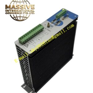
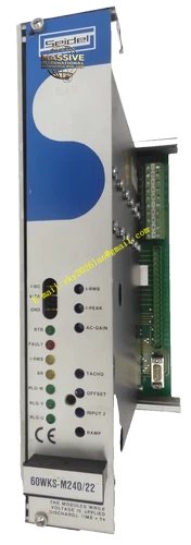
Kollmorgen 60WKS-CE240 22PB
Technical Specifications
- Series: 60WKS Analog Servo Amplifier Series
- Input Voltage: Three-phase 60 to 172 VAC, 50/60 Hz with plus or minus 10 percent tolerance
- Rated DC-Link Voltage: 240 VDC
- Peak Output Current: 22 Amps
- Rated Output Current: 22 Amps continuous
- Installed Load Capacity: 3.7 kVA
- Ballast Circuit Pulse Power: 5.4 kW
- Ballast Circuit Continuous Power: 135 W
- Minimum Motor Inductance: 0.7 millihenries
- Control Method: Analog PI current and speed control
- Commutation: Trapezoidal commutation for brushless motors
- Feedback: RLG resolver and DC tachometer inputs
- Logic Interface: 24 VDC with isolated optocouplers, PLC-compatible
- Protection: Overvoltage, undervoltage, overcurrent, short-circuit, earth fault, and thermal monitoring
- Operating Temperature: 0 degrees Celsius to plus 40 degrees Celsius
- Protection Rating: IP00, requires installation in closed switchgear cabinet
- Humidity: 5 percent to 85 percent relative humidity
Functional Features
- Three-phase PWM transistor output stage for 4-quadrant operation
- Two differential setpoint inputs with setpoint 2 individually adjustable
- Enable input for secure system integration
- Electronic rotor position sensor input controlling motor phase switching
- Ballast circuit with characteristic-w for regenerative energy dissipation
- Ready/standby relay with isolated contact for fault signaling
- LEDs for all important operating states
- Expansion slot for optional PCB with limit-switch logic and ramp generator
- Custom PCB containing all user-adjustable parameters
- Servo motor brake control function for 24 VDC maximum 1.5 Amp brakes
Application Scenarios
- Medium-duty CNC machine tools
- Industrial robotics and positioning systems
- Packaging and printing machinery
- Automated material handling
- Legacy systems requiring 22 Amp analog servo control
Performance Parameters
- 22 Amp peak current supports larger frame SM series motors
- 3.7 kVA installed load capacity for medium-power applications
- Fast dynamic response through analog PI control loops
- Reliable trapezoidal commutation with resolver feedback
Material Composition and Structure
- Steel chassis construction with 19-inch rack-mount housing option
- Aluminum front panel with custom PCB
- Integrated smoothing capacitors and ballast resistor
- Heavy-duty terminal blocks rated for 22 Amp industrial power
- Status LEDs for power, fault, and operational state indication
Working Principle The amplifier converts three-phase AC input to a regulated 240 VDC bus through internal rectification and smoothing. Analog PI controllers process speed setpoints against tachometer feedback, generating current commands for the trapezoidal commutation stage. The electronic rotor position sensor ensures proper phase sequencing for the brushless motor. During braking, regenerated energy is dissipated through the ballast resistor, with the ballast circuit activating at 285 VDC and rising to 300 VDC under repeated loading.
Installation Requirements
- Mount in closed switchgear cabinet with 0 to 40 degrees Celsius ambient control
- Connect to three-phase isolating transformer with 60 to 172 VAC output
- Use twisted and shielded cables for setpoint, tacho, and motor power
- Earth DC-link through dedicated PE connection
- Connect all earth leads to a common star point to prevent ground loops
- Loop BTB contact into system safety circuit for controller-ready monitoring
Operating Precautions
- Do not switch on operating voltage before verifying rated voltage matches transformer and motor data
- Ensure maximum 43 VAC on terminals 20, 22, 32 is not exceeded to prevent ballast circuit destruction
- Provide forced convection fan for rated currents above 8 Amps
- Maintain vertical mounting position for proper thermal management
- Wait 120 seconds after power-off before servicing due to capacitor residual charge