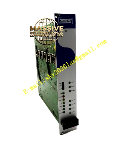
Description
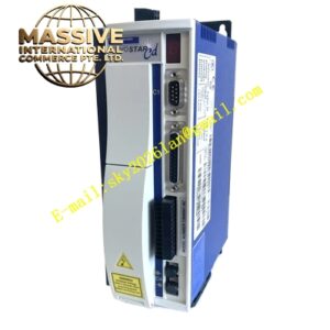
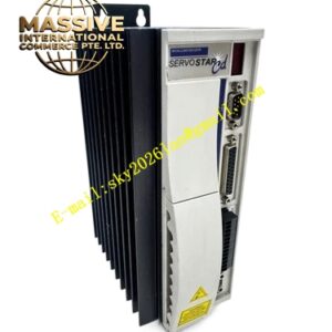
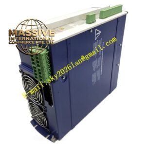
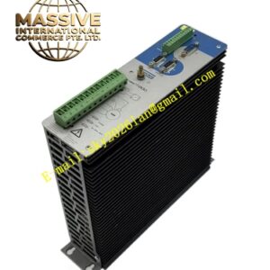
Kollmorgen 60WKS-M240 12-PB
Technical Specifications
- Series: 60WKS Analog Servo Amplifier Series
- Input Voltage: Three-phase 60 to 172 VAC, 50/60 Hz with plus or minus 10 percent tolerance
- Rated DC-Link Voltage: 240 VDC
- Peak Output Current: 12 Amps
- Continuous Output Current: 6 Amps
- Ballast Circuit Pulse Power: 5.4 kW
- Ballast Circuit Continuous Power: 135 W
- Control Method: Analog PI current and speed control
- Commutation: Trapezoidal commutation
- Feedback: RLG resolver and DC tachometer inputs
- Logic Interface: 24 VDC with isolated optocouplers
- Protection: Overvoltage, undervoltage, overcurrent, thermal monitoring
- Operating Temperature: 0 degrees Celsius to plus 40 degrees Celsius
- Protection Rating: IP00
Functional Features
- Three-phase PWM transistor output stage
- Two differential setpoint inputs
- Enable input for system integration
- Electronic rotor position sensor input
- Ballast circuit for regenerative braking energy
- Ready/standby relay with isolated fault contact
- LEDs for operating state indication
- Expansion slot for optional limit-switch and ramp generator PCB
Application Scenarios
- Small to medium CNC retrofits
- Industrial positioning equipment
- Packaging machinery
- Automated assembly systems using SM series motors
Performance Parameters
- 12 Amp peak current for small to medium frame servo motors
- Stable analog control with PI compensation
- Reliable trapezoidal commutation
Material Composition and Structure
- Steel and aluminum chassis with integrated heatsink
- Modular PCB architecture
- Heavy-duty terminal blocks
- Status LED indicators
Working Principle The amplifier rectifies three-phase input to establish a 240 VDC bus. Analog PI controllers compare setpoint signals against tachometer feedback, generating current commands for the PWM output stage. The rotor position sensor ensures correct electronic commutation sequencing for the brushless motor.
Installation Requirements
- Install in closed electrical enclosure
- Connect to three-phase isolating transformer
- Use shielded cables for feedback and power
- Ensure proper grounding of DC-link
Operating Precautions
- Verify voltage ratings before energizing
- Allow capacitor discharge time after power-off
- Maintain adequate ventilation
- Monitor thermal status during operation