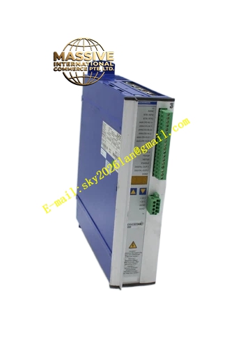
Description
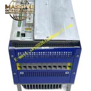
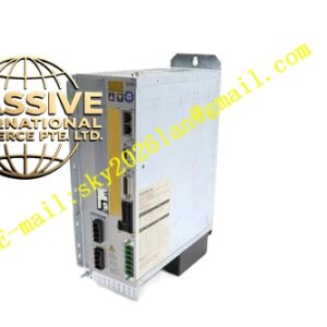
Kollmorgen BDS5A-220-00010
Technical Specifications
- Input Voltage: 230 VAC nominal, three-phase
- Main DC Bus Voltage: 225 VDC nominal, with operational capability down to 130 VDC without tripping
- Continuous Output Current: 20.0 Amps RMS per phase
- Peak Output Current: 40.0 Amps RMS for 2.0 seconds
- PWM Carrier Frequency: 10 kHz
- Current Ripple Filter: 20 kHz
- Resolver Excitation: 8.5 kHz
- Resolver-to-Digital Accuracy: 8 arc-minutes
- Position Resolution: 12 bits, providing 4,096 counts per revolution
- I/O Capacity: Up to 32 general-purpose I/O points for limit switches, enables, and fault contacts
- Communication: RS-232 serial interface for parameter configuration and status reporting
- Feedback: Primary resolver feedback with additional encoder input channel for incremental feedback sources
- Cooling: Onboard fan drawing 0.2 Amps at 115 VAC for semiconductor thermal management
Functional Features
- Velocity mode operation with analog command input
- Torque modulation through high-frequency PWM output stage
- Synchronized resolver excitation and feedback sampling
- Dual feedback capability supporting both resolver and incremental encoder simultaneously
- Hardware overtravel and fault protection through discrete I/O
- Status monitoring and parameter download via serial communication
- Ride-through capability for moderate line voltage dips
Application Scenarios
- Large indexing tables and rotary positioning systems
- Heavy-duty material handling and conveyor equipment
- High-inertia feeder tracks
- Industrial machinery requiring 20 Amp continuous servo power
- Machine tools with substantial cutting loads
Performance Parameters
- 2:1 peak-to-continuous current ratio delivers aggressive acceleration profiles
- 10 kHz PWM carrier ensures smooth current delivery with low harmonic distortion
- 20 kHz ripple filtering limits electromagnetic interference
- High current output supports motors with continuous torque requirements exceeding 10 Nm
Material Composition and Structure
- Industrial steel and aluminum chassis with integrated heatsink
- Modular power stage design using high-current semiconductor switches
- Isolated logic and power sections for noise immunity
- Heavy-duty terminal blocks rated for 20 Amp continuous industrial power
- Removable terminal connectors for field wiring maintenance
Working Principle The drive rectifies incoming three-phase AC power to establish a regulated DC bus at 225 VDC. The PWM inverter stage synthesizes three-phase sinusoidal current at 10 kHz carrier frequency to drive brushless permanent magnet motors. A resolver mounted on the motor shaft provides absolute position feedback, excited at 8.5 kHz and converted to digital position data with 12-bit resolution. The velocity control loop compares analog command input against actual velocity derived from position feedback, generating current commands for the inner torque loop. The drive conditions power so external controllers can impose rapid speed changes without mechanical relays.
Installation Requirements
- Mount in NEMA-rated electrical enclosure with minimum IP54 protection
- Maintain six inches of clearance around heatsink and fan exhaust for adequate airflow
- Connect three-phase 230 VAC supply with appropriate circuit protection
- Use shielded cables for motor power, resolver feedback, and encoder signals
- Ensure proper grounding of all conductive surfaces per electrical code standards
Operating Precautions
- Verify input voltage matches 230 VAC nominal rating before energizing
- Confirm motor current ratings are compatible with 20 Amp continuous and 40 Amp peak output
- Allow two-second peak current duty cycle to prevent thermal overload shutdown
- Monitor DC bus voltage during operation to ensure it remains above 130 VDC
- Only qualified personnel should perform installation and commissioning