Description
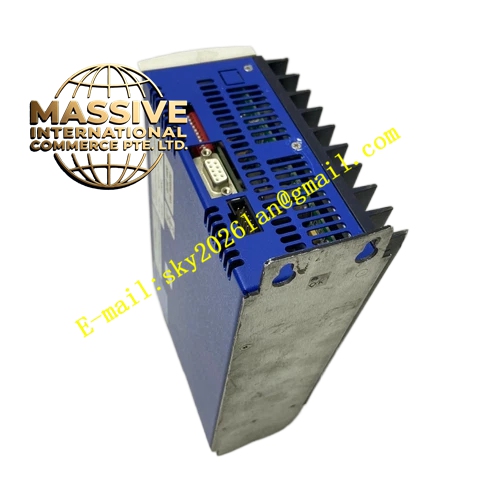
Kollmorgen CR062513
- Technical Specifications
- Input Power: Single‑phase 115 / 230 VAC, 47‑63 Hz
- Rated Continuous Output Current: 6 A RMS
- Peak Output Current: 18 A RMS (0.5 second duration)
- Apparent Power Rating: 1.8 kVA at 115 VAC, 2.8 kVA at 230 VAC
- Auxiliary Logic Supply: 22‑27 VDC
- Analog Monitoring Output: ±10 V, 12‑bit resolution
- Cooling Method: Natural convection via large‑area integrated aluminum heat sink
- Protection Class: IP20
- Weight: 3.4 kg
- Functional Features
- Hybrid analog control circuit plus digital fault‑detection logic
- Supports torque‑control mode, velocity‑control mode, external step‑direction position reference mode
- 12‑bit analog monitoring output for real‑time torque or velocity signal external measurement
- Comprehensive hardware protection: over‑current, over‑voltage, under‑voltage, motor winding short‑circuit, heat‑sink overtemperature, feedback‑circuit breakage detection
- Open‑collector fault relay output with 3 ms fault‑contact closing time
- Multiple on‑board trimming potentiometers for current‑loop gain, velocity‑loop gain, velocity offset, dead‑zone adjustment
- Integrated high‑capacity dynamic brake circuit for rapid deceleration of medium‑inertia loads
- No native fieldbus interface, motion command comes from analog voltage or pulse‑direction signals
- Application Scenarios: Medium‑load legacy packaging‑machine axes, printing converting‑equipment retrofitting, textile processing‑machine main auxiliary axes, special‑purpose industrial test‑bench drives, production‑line upgrade projects keeping original analog host‑controller architecture
- Performance Parameters: Velocity‑loop bandwidth up to 420 Hz; current‑loop hardware response time below 12 µs; analog command resolution 4.9 mV; compatible with DC tachometer and incremental encoder feedback devices
- Material Composition: Large‑size anodized aluminum extruded heat sink, reinforced cold‑rolled steel sheet‑metal enclosure, FR‑4 high‑temperature printed‑circuit boards, high‑current bipolar power transistors, large‑capacity wound electrolytic power capacitors, reinforced plastic barrier terminal blocks, carbon‑film trimming potentiometer group
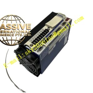
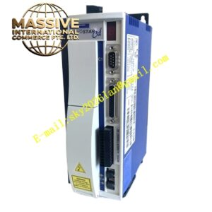
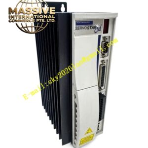
- Structural Characteristics: Horizontal cabinet‑panel‑mount metal housing; physical isolation between internal high‑power power‑circuit zone and low‑voltage signal zone; heavy‑duty barrier screw terminals for power‑circuit wiring; D‑Sub multi‑pin connector for tachometer and encoder feedback; top‑surface removable access cover for potentiometer manual adjustment; reinforced mounting holes for panel installation under vibration‑prone industrial environments.
- Working Principle: Single‑phase AC input is rectified to produce stable DC‑link bus voltage; analog error amplifier compares external motion‑command signal with real‑time motor velocity or torque feedback signal; power output stage generates adjustable‑magnitude DC current to drive brush‑type permanent‑magnet servo motor; tachometer or incremental encoder transmits real‑time motor operating feedback back to control circuit; dedicated fault‑monitoring hardware continuously samples bus voltage, output current and heat‑sink temperature, activates fault‑signal output and cuts power‑stage output immediately upon fault conditions.
- Installation Requirements: Horizontal panel‑mount installation inside control cabinet; maintain sufficient surrounding free‑space for natural convection heat dissipation; avoid mounting adjacent to other high‑heat‑emitting power components; protective‑earth terminal must connect firmly to cabinet protective‑ground bus; operating ambient temperature range 0‑40 °C; performance derating applies for altitude higher than 1000 m.
- Usage Notes: Complete protective‑earth connection before applying main‑power input; do not energize without motor‑load connection; adjust gain‑setting potentiometers incrementally to suppress mechanical oscillation and resonance; execute capacitor reforming process if storage duration exceeds 12 months; prevent conductive‑dust accumulation and internal condensation; enclosure cover must remain closed during equipment runtime; verify tachometer and encoder feedback wiring completely before commissioning.