Description
Kollmorgen RMB‑10V2‑SYNQNET
Functional Features: Bridge analog‑servo drives into SynqNet digital motion‑network; four‑axis independent analog‑command DAC output; incremental‑encoder feedback acquisition with broken‑wire‑fault detection; opto‑isolated digital‑I/O for limit, home, amplifier‑fault and enable‑signal; analog‑input signal acquisition; SynqNet ring‑topology network communication; front‑panel multi‑channel status‑LED indicators; real‑time fault‑diagnosis reporting over SynqNet bus.
Application Scenarios: Retrofit‑upgrade of legacy analog‑servo‑based automation‑machinery; test‑platforms mixed with analog‑drives and SynqNet‑digital‑drives; old‑style machine‑tool renovation‑projects; spare‑part replacement for existing SynqNet‑networked analog‑drive‑systems.
Performance Parameters: DAC resolution 16‑bit; encoder‑input maximum frequency 10 MHz; broken‑wire‑detection for encoder channels; SynqNet cyclic‑data update cycle configurable down to 125 μs; opto‑isolated channel isolation voltage 2500 Vrms.
Material Composition: Green DIN‑rail plastic housing; multi‑channel high‑precision DAC‑ADC chips; FPGA logic‑processing chip; opto‑coupler isolation‑components; gold‑plated industrial‑connectors; flame‑retardant PCB circuit board; status‑LED indicator array; RJ45 SynqNet transceiver modules.
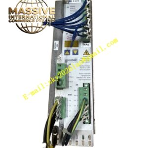
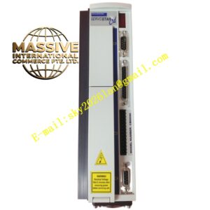
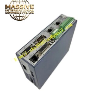
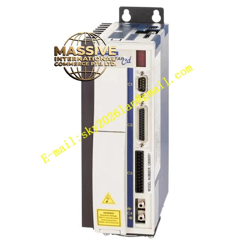
Structural Features: Compact DIN‑35 rail‑mount housing; front‑panel multi‑channel status‑LED indicators; two RJ45 SynqNet ring‑network connectors; side‑mount multi‑pin signal‑connectors for axes‑0‑1 and axes‑2‑3; 24 VDC power‑input terminal; no internal fan, convection‑cooling structure.
Working Principle: SynqNet motion‑controller sends digital motion‑set‑point commands over SynqNet ring‑network to RMB‑10V2‑SynqNet node. On‑board FPGA converts digital‑set‑point value into ±10 V analog‑voltage via 16‑bit DAC chip, and outputs analog‑command signal to external analog‑servo‑amplifier. Encoder feedback signals from motor are received by differential‑encoder‑input circuit, and encoder‑position‑data is transmitted back to SynqNet‑controller. Digital‑limit, home, amplifier‑fault and enable‑signals are processed through opto‑isolation circuits, and status‑information is uploaded over SynqNet bus. Broken‑wire‑detection circuit monitors encoder‑cable integrity continuously.
Installation Requirements: Vertically mount on DIN‑35 rail inside IP20 industrial‑control cabinet; maintain 20 mm upper‑lower and 10 mm left‑right ventilation clearance; SynqNet ring‑network uses shielded industrial‑Ethernet‑cable; separate analog‑signal cables and power‑cables with physical spacing; connect unit protective‑earth terminal to cabinet grounding‑bar reliably; 24 VDC power‑supply must provide stable and isolated logic‑power; strictly follow SynqNet ring‑topology wiring‑rules.
Usage Notes: This hardware only supports SynqNet Phase 2 software environment; do not hot‑swap signal‑connectors while system is powered‑on; avoid analog‑signal‑cable running parallel with high‑power‑cables; regularly verify encoder‑broken‑wire‑detection function; spare‑part replacement must confirm firmware‑version matches existing SynqNet‑controller system.