Description
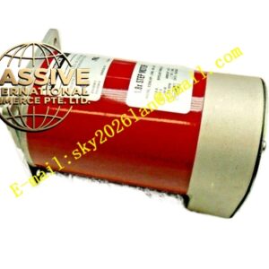
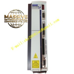
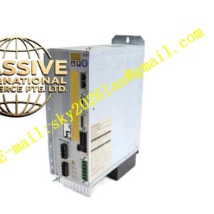
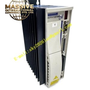
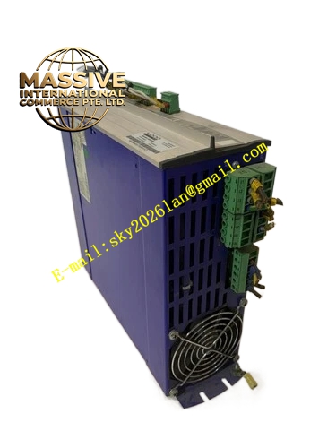
Kollmorgen S400446‑M
Technical Specifications:
- Rated supply voltage: 3×230V‑10% ~ 3×400V+10%, 50/60HzKollmorgen
- Rated installed S1 operation power: 12 kVAKollmorgen
- Rated output RMS current: 6 A; Peak output current (max 5s): 12 A
- DC‑link voltage range: 310‑560 VDCKollmorgen
- Internal continuous regeneration power: 40 W; Max external continuous regeneration power: 400 W; Peak external regeneration power: 16 kWKollmorgen
- Protection rating: IP20, cabinet‑mount installation only
- Dimension: 230 mm × 100 mm × 230 mm; Weight: 3.38 kg
- Control loop bandwidth: Current controller bandwidth >1.2 kHz; PWM cycle 62.5 µs
- Auxiliary control supply: 24 VDC Functional Features:
- Master‑axis function, provides shared DC‑bus for up to 7 slave A‑axis units, realizes dynamic regenerative power distribution among connected drivesKollmorgen.
- Multi‑feedback support: HIPERFACE, EnDat, resolver, incremental encoder with Hall sensors, ComCoder feedback devices are compatible.
- Built‑in CANopen fieldbus interface; RS232 service port for PC software commissioning and parameter download; optional PROFIBUS, SERCOS interface via hardware option cardsKollmorgen.
- Embedded programmable digital & analog I/O: 4 digital inputs, 2 digital outputs, 1 analog input; supports encoder emulation function for incremental and SSI absolute signal outputKollmorgen.
- Complete hardware protection: over‑voltage, under‑voltage, over‑current, short‑circuit, motor overload, over‑temperature monitoring and fault latch indication with LED status indicators.
- Space‑vector pulse‑width modulation algorithm, supports torque, velocity and position closed‑loop control modes. Application Scenarios: Multi‑axis packaging machinery, printing converting equipment, textile production lines, automated assembly stations, gantry motion systems, machine tool auxiliary axes, material handling automation requiring tight multi‑axis synchronization. Material Composition: Die‑cast aluminum alloy housing for thermal dissipation; FR4 printed circuit board with power IGBT power modules; plug‑gable green spring‑cage terminal blocks; metal shielding shell; internal aluminum heat sink; surface‑mount electrolytic and film capacitors. Structural Characteristics: Vertical cabinet DIN‑rail mounting structure; front‑side accessible terminal connectors; status LED indicator on front panel; internal heat sink arranged along airflow direction; separate power section and control section layout for EMI suppression. Working Principle: AC mains input is rectified into DC‑bus voltage by internal power stage. DSP controller receives setpoint commands from fieldbus or analog I/O, computes output via PID control loops, drives IGBT power stage to generate three‑phase variable‑frequency variable‑voltage AC for servo motor. Motor feedback signal is sampled for closed‑loop correction. Regenerative energy from motor deceleration is dissipated by internal brake resistor or transferred to other axes over shared DC‑busKollmorgen. Installation Requirements:
- Install inside IP54 or higher industrial control cabinet, vertical mounting orientation only.
- Maintain upper and lower clearance ≥100 mm for convection cooling; side‑to‑side clearance ≥20 mm between adjacent drives.
- Maximum installation altitude 1000 m without derating; above 1000 m derate output power by 2.5 % per 300 m elevation increase.
- Power cable and feedback cable must use shielded wiring, shield ground connected to drive shielding clamp.
- Same mains supply must be used for all drives connected to shared DC‑bus; total summation of RMS current of slave axes shall not exceed 40 A