Description
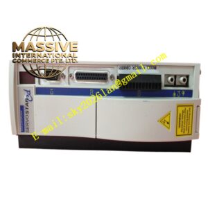
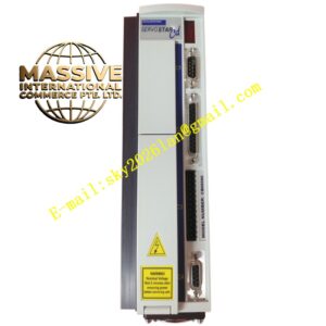
Kollmorgen S610-30
Technical Specifications
- Product Family: SERVOSTAR 600 (Standard Version)
- Device Designation: SERVOSTAR 610-30
- Rated Supply Voltage: 3 x 230 V to 480 V, 50 Hz (+10%/-10%) or 3 x 208 V to 480 V, 60 Hz (+10%/-10%)
- Auxiliary Supply Voltage: 24 VDC, electrically isolated, internal fusing (3.15 AT)
- Certifications: UL (cUL) listed under file number E217428, UL 840, UL 508C, CE, GOST-R
Functional Features
- Digital Servo Control: Provides precise torque, speed, and position control through cascaded digital control loops
- Multiple Feedback Support: Compatible with resolvers, sine encoders (with BiSS, EnDat 2.1, Hiperface), incremental encoders, and Hall sensors
- Fieldbus Connectivity: Supports CANopen (DS301/DS402), with optional expansion cards for PROFIBUS, SERCOS, DeviceNet, EtherCAT, and SynqNet
- Electronic Gearing: Supports master-slave operation with up to 16 slave amplifiers
- Setup Software: Configurable via DRIVE.EXE setup software through RS232 serial interface
- Analog and Digital I/O: Two differential analog inputs, analog outputs (10 bit resolution, 62.5 µs update rate), digital inputs (IEC 61131-2 Type 1), and digital outputs (open-collector and relay)
Application Scenarios
- Industrial Automation: Production line control, material handling, packaging machinery
- Machine Tools: CNC machine tools, cutting and forming equipment
- Medical Equipment: Medical imaging devices, surgical robots
- Semiconductor Manufacturing: Precision positioning in semiconductor production equipment
- Multi-Axis Systems: Up to six amplifiers can be connected together using special multilink cables
Performance Parameters
- Brake Circuit Upper Switch-On Level: 400–430 V (for 606–620 class models)
- Brake Circuit Switch-Off Level: 380–410 V
- Analog Output Resolution: 10 bit
- Analog Output Update Rate: 62.5 µs
- Digital Input Standard: IEC 61131-2 Type 1 (High: 11–30 V, Low: -3 to +5 V)
Material Composition
- Metal housing with integrated electronic components including IGBT power stage, digital signal processor, and brake resistor circuit
Structural Features
- Mounting: 2 or 4 hexagon socket screws (M5), requiring a 4 mm Allen key
- Connectors: Mating connectors X3, X4, X0A, X0B, X7, X8 included; SubD connectors and motor connector X9 not included
- LED Display: Front panel LED display for status, error codes, and warning messages
- Connector Torque: X3, X4: 0.5 to 0.6 Nm; X0A, X0B, X7, X8, X9: 0.5 to 0.6 Nm; Ground bolt: 3.5 Nm
Working Principle
The S610-30 receives 3-phase AC input power, converts it to DC bus voltage, and drives the brushless servo motor through its IGBT power stage. Cascaded digital control loops (current, velocity, position) provide precise torque, speed, and position control. The feedback device monitors the motor’s rotor position and speed, and the drive continuously adjusts the supplied current and voltage to correct any deviations from the commanded motion.
Installation Requirements
- Mounting inside a closed switchgear cabinet
- Proper EMC-compliant grounding and shielding for all cables (do not use painted/non-conductive mounting plates)
- External fusing required for AC supply protection
- 24 VDC auxiliary supply from an external power source with insulating transformer
- Wait at least 5 minutes after disconnecting from main supply before touching potentially live sections
- For motor cable lengths above 25 m, a choke box must be wired into the motor lead close to the amplifier
Usage Notes
- Verify motor voltage and current ratings match the drive specifications
- Monitor thermal conditions during continuous operation
- Back up drive configuration parameters regularly
- Never undo electrical connections while the drive is live
- In multi-axis systems, set up each servo amplifier individually
- The machine builder must generate a hazard analysis for the complete machine