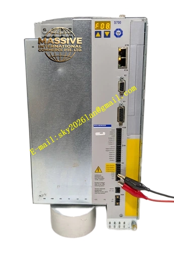
Description
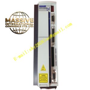
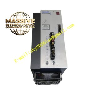
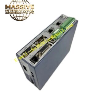
Kollmorgen S74802‑NANANA
Technical Specifications: ‑ Input Power Supply: 3‑phase 208‑480 VAC ‑ Continuous Output Current: 48 A RMS ‑ Peak Output Current: 96 A RMS for 5 seconds ‑ Control Supply Voltage: 24 V DC ±20% ‑ Safety Function: Dual‑channel Safe Torque‑Off STO SIL2 PL d ‑ Fieldbus Interfaces: EtherCAT, CANopen; supports optional expansion for PROFINET, DeviceNet ‑ Feedback Interfaces: EnDat 2.2, BiSS‑C, HIPERFACE, resolver, SFD3 single‑cable feedback ‑ Digital Inputs: 6 optically isolated digital inputs ‑ Digital Outputs: 2 optically isolated digital outputs ‑ Analog Inputs: 2 analog inputs ±10 V ‑ Analog Outputs: 2 analog outputs ±10 V ‑ Memory Medium: MMC memory card slot for parameter backup and firmware update ‑ Cooling Method: Forced air convection cooling ‑ Installation Form: DIN rail cabinet mounting ‑ Operating Ambient Temperature: 0 °C to +55 °C ‑ Storage Temperature: ‑25 °C to +70 °C ‑ Protection Class: IP20 for cabinet‑only installation ‑ Compliance Certification: CE, UL, RoHS, REACH
Functional Features: ‑ High‑bandwidth current, velocity and position control loops deliver fast dynamic motion response ‑ Dual‑channel hardware STO safety function cuts motor torque output without power‑supply disconnection ‑ Wide motor compatibility covers synchronous, asynchronous, spindle and linear motor types ‑ Supports single‑cable SFD3 feedback architecture to reduce field wiring quantity and wiring errors ‑ Built‑in IEC 61131‑3 macro programming capability for custom motion logic implementation ‑ MMC card realizes one‑click parameter cloning and firmware upgrade for batch machine commissioning ‑ Integrated brake chopper circuit handles regenerative energy from decelerating motor loads ‑ Over‑current, over‑voltage, under‑voltage, over‑temperature, motor‑short‑circuit fault detection built‑in ‑ LED status indicators display operating state, warning codes and fault codes directly on front panel ‑ Full parameter configuration via Kollmorgen WorkBench PC software
Application Scenarios: Applied for high‑dynamics industrial automation equipment including printing machinery, packaging production lines, machine‑tool auxiliary axes, robotic auxiliary mechanisms, textile processing equipment, material handling gantry systems and test‑bench motion simulators. Installed inside industrial control cabinets for general factory automation environments.
Performance Parameters: ‑ Current loop bandwidth: Max 4 kHz ‑ Velocity loop bandwidth: Max 800 Hz ‑ Position loop bandwidth: Max 250 Hz ‑ Position resolution depends on selected feedback device, up to 23‑bit encoder resolution ‑ Short‑circuit protection response time less than 2 μs ‑ STO safety response time below 2 ms ‑ Maximum pulse frequency for pulse‑direction command input reaches 1 MHz
Material Composition: ‑ Main housing: Cold‑rolled steel sheet with black powder‑coated surface treatment ‑ Internal power module substrate: Insulated metal substrate for power semiconductors ‑ Power semiconductor devices: IGBT power switches ‑ Signal circuit board: FR‑4 glass‑epoxy printed circuit board ‑ Terminal blocks: Nylon‑based flame‑retardant plastic with tin‑plated copper contacts ‑ Heat sink: Extruded aluminum alloy ‑ Front‑panel protective cover: Polycarbonate flame‑retardant plastic
Structural Features: ‑ Vertical compact cabinet‑mount structure, standardized DIN‑rail clamping mechanism at bottom rear side ‑ Independent separation layout for high‑power power circuit area and low‑voltage signal circuit area to reduce electromagnetic interference coupling ‑ Front‑side accessible terminal blocks for power supply, motor power, feedback signal and digital‑analog I/O connection ‑ Front‑mounted LED status indicator array and MMC card slot ‑ Internal aluminum heat sink arranged behind power module for forced‑air heat dissipation; cooling airflow passes through internal heat‑dissipation channel without blowing over signal circuit boards ‑ Expansion slots reserved for optional communication interface modules.
Working Principle: Three‑phase AC mains input converts to DC bus voltage via internal rectifier circuit. IGBT power inverter converts DC bus voltage into adjustable‑amplitude adjustable‑frequency three‑phase AC output to drive connected servo motor. Feedback device transmits motor rotor position and velocity real‑time data back to drive control board. Internal digital processor executes closed‑loop position, velocity and torque algorithm according to host controller setpoint commands. Dual‑channel STO hardware circuit directly disables IGBT gate drive signal to cut motor torque output when safety trigger condition activates. Brake chopper consumes regenerative energy generated during motor deceleration process to stabilize DC bus voltage.
Installation Requirements: ‑ Install device inside closed IP54 or higher industrial electrical cabinet. Outdoor installation is prohibited. ‑ Mount vertically on standard DIN rail. Horizontal or upside‑down mounting orientation is strictly forbidden. ‑ Maintain minimum clearance of 50 mm above and below drive unit for cooling air circulation. Keep 20 mm clearance on left and right sides. Do not stack multiple drives without spacing. ‑ Connect protective earth PE terminal with low‑impedance ground wire of cabinet ground bus bar. ‑ Power‑cable shielding layers must connect to dedicated shielding terminals on drive housing. ‑ Separate high‑power motor power wiring from low‑voltage signal wiring with minimum 100 mm distance to avoid electromagnetic interference coupling. ‑ Control 24 V DC auxiliary power supply must provide isolated safety extra‑low‑voltage SELV output. ‑ Dual‑channel STO input terminals must be wired in accordance with SIL2 safety circuit requirements. Short STO inputs directly to 24 V DC if safety function is not used. ‑ Cabinet internal ambient temperature cannot exceed +55 °C during continuous running. Install cabinet cooling fan if multiple high‑power drives work simultaneously.
Usage Notes: ‑ Do not open drive housing cover. Internal high‑voltage DC bus capacitor holds dangerous residual voltage after main power supply switches off. Wait at least 10 minutes after power‑off before touching internal components. ‑ Strictly match motor rated parameters with drive output rating. Do not connect motors with far‑exceeding or insufficient power rating. ‑ Complete full insulation resistance test for motor power cable before power‑on commissioning. Short‑circuit condition will destroy internal power module. ‑ Do not perform hot‑plugging for motor power connector and feedback connector under energized state. ‑ Save complete parameter backup file to MMC card or PC storage after commissioning completion. ‑ Do not operate this equipment inside explosive hazardous‑area atmosphere. ‑ Regularly inspect cooling fan running condition and heat‑sink dust accumulation during scheduled machine maintenance. Dust‑blocked heat sink will trigger over‑temperature fault. ‑ Any repair work must be completed by authorized Kollmorgen service personnel. Unauthorized disassembly voids product warranty.