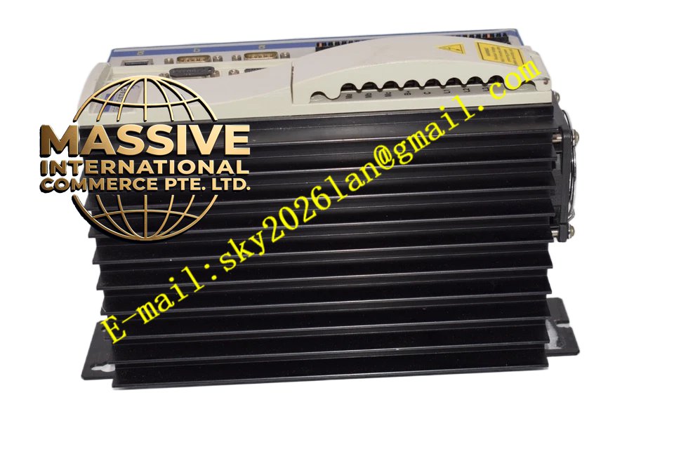
Description
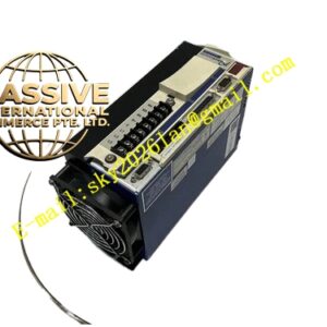
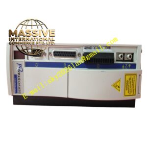
Kollmorgen SC1R10260
Technical Specifications
| Parameter Category | Specific Specification |
|---|---|
| Manufacturer | Kollmorgen (Danaher Motion) |
| Product Family | SERVOSTAR SC Series |
| Power Supply | 1/3-Phase, 115/230 VAC nominal |
| Input Current | 14/10 Amps per phase (115/230 VAC) |
| Input Power | 2.3/3.5 kVA (115/230 VAC) |
| Output Voltage | 115/230 VAC |
| Output Current | 10.0 Amps RMS continuous per phase |
| Peak Output Current | 20.0 Amps RMS (2 seconds) |
| Output Power | 1.7/3.0 kVA (115/230 VAC) |
| PWM Frequency | 8 kHz |
| Control Modes | Position, velocity, torque (position control standard) |
| Command Interface | ±10V analog, step/direction, indexer, CANopen |
| Feedback | Resolver (standard), incremental encoder (optional) |
| Position Control | Built-in indexer with 64 motion profiles |
| I/O | 4 digital inputs, 2 digital outputs, 1 analog input |
| Protection | Overcurrent, overvoltage, undervoltage, overtemperature, position error |
| Operating Temperature | 0°C to +45°C |
| Storage Temperature | -25°C to +70°C |
| Protection Class | IP20 |
Key Features
- Higher Power Position Control: 10A continuous output drives larger positioning mechanisms while maintaining integrated control
- Built-In Indexer: 64 pre-programmed motion profiles stored in non-volatile memory eliminate external controller need
- Flexible Command Interface: Accepts analog, step/direction, or CANopen commands for versatile system integration
- Robust Resolver Feedback: Standard resolver interface provides reliable position feedback in harsh environments
- Compact Footprint: Space-saving design suitable for distributed control architectures
- Auto-Tuning Capability: Automatic parameter adjustment reduces commissioning time and expertise requirements
- CANopen Network Ready: Standard CANopen interface enables integration into industrial fieldbus networks
Application Scenarios
- Medium positioning systems: Drives larger linear stages, rotary indexing tables, and gantry positioning systems
- Packaging lines: Controls carton erectors, case packers, and palletizing stations with complex motion sequences
- Automated assembly: Powers screw driving stations, part insertion mechanisms, and quality inspection positioning
- Metal fabrication: Controls press brake backgauges, punch press positioning, and material feed systems
- Plastics machinery: Drives core pull, eject, and mold adjust positioning in injection molding
- Printing and labeling: Controls web registration, die cutting, and label application positioning
- Test and measurement: Powers test fixture positioning, sample handling, and inspection stages
- Converting machinery: Drives slitter positioning, rewind arm control, and tension roller adjustment
Performance Parameters The SC1R10260 maintains the SC series position loop update rate of 1 millisecond with 32-bit resolution. The velocity loop bandwidth is 400 Hz. The current loop bandwidth is 1.5 kHz with enhanced current capacity. Positioning accuracy remains within ±1 encoder count. The indexer supports all standard motion profile types including S-curve acceleration for smooth motion. Home search supports limit switch, home sensor, and encoder index methods with programmable approach velocities. Electronic gearing ratio range is 1:32768 to 32768:1. The drive supports cam table execution with up to 1000 points.
Material Composition The drive enclosure is constructed from aluminum with industrial-grade powder coating. Power semiconductors are higher-capacity IPM packages than the 6A model. The control board uses a 4-layer PCB with enhanced copper traces for 10A current handling. DC bus capacitors are higher-grade electrolytic types with increased ripple current capacity. The heat sink is a larger extruded aluminum profile with increased surface area. Front panel is durable plastic with LED indicators. Internal firmware is stored in flash memory with battery-backed RAM.
Structural Characteristics The drive features a compact rectangular enclosure slightly larger than the 6A model. Power terminals are higher-capacity screw-type spring clamps accepting wire up to 4 mm². Control connectors are pluggable terminal blocks. The front panel includes comprehensive status LEDs (power, run, fault, position ready, indexer active) and a serial communication port. Internal layout optimizes thermal management with the power stage thermally coupled to the heat sink. Cooling is by natural convection with integral fan for high-duty applications. Mounting options include DIN rail clip and panel mounting feet.
Working Principle AC input is rectified and filtered to DC bus voltage (160 VDC for 115V input, 325 VDC for 230V input). The IPM inverter generates variable-frequency three-phase output under DSP control. The integrated position controller executes the indexer function, managing motion profiles stored in memory. Resolver feedback is converted to absolute position by the RDC circuit. The position loop closes by comparing profile position against actual position. Velocity and current loops cascade below the position loop for stable control. The indexer can execute conditional motion based on input states and trigger outputs at programmed positions, enabling stand-alone machine control.
Installation Requirements
- Mount on DIN rail or panel surface with minimum IP20 protection
- Provide minimum 50 mm clearance on all sides for heat dissipation
- Connect power through circuit breaker rated for 16A (115V) or 10A (230V)
- Use motor power cables of 2.5 mm² minimum cross-section
- Connect resolver feedback using shielded twisted pair cable
- Ground shield at drive end only to prevent ground loops
- Separate power and control cables by minimum 150 mm
- Configure and program using MotionLink software via serial interface
- Define all motion profiles, position limits, and I/O functions before operation
- Verify home switch and limit switch functionality before enabling motion