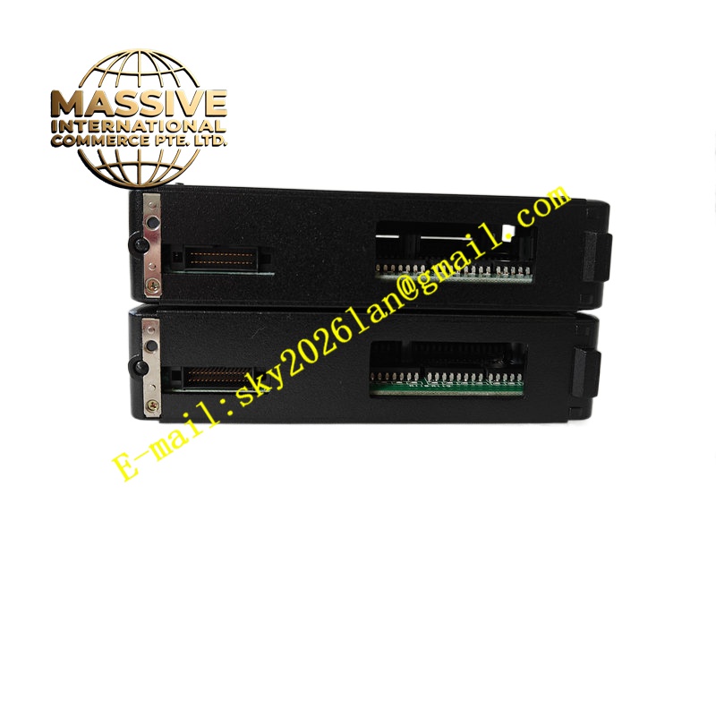
Description
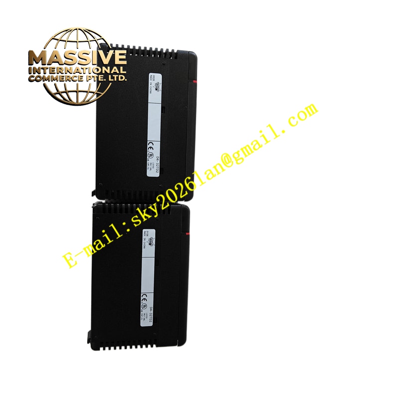
KOYO D4-32TD2
Technical Specifications 32 total digital I/O points; DC signal level 24 V; optocoupler isolation between field side and rack backplane; removable screw terminal blocks; backplane connector for D4 rack bus; operating temperature 0 ℃ to +60 ℃; protection class IP20 for cabinet installation; maximum input and output current per channel conforming to D4 series ratings.
Functional Features Hardware opto-isolation suppresses field noise and ground offset; per-channel status LED indicates on/off state; automatic data refresh over rack backplane; overcurrent protection on output channels; fault indication for power loss to field I/O circuit.
Application Scenarios Material handling conveyor racks, automotive assembly fixture control, packaging line I/O expansion, factory machine safety signal marshalling.
Material Composition Flame-retardant plastic module housing; FR4 digital signal PCB; optocoupler isolation devices; gold-plated backplane edge connector; plastic removable terminal blocks with spring-clamp screw terminals.
Structural Characteristics Rack plug-in module form; front panel with per-channel LED indicators; rear edge gold finger connects to D4 rack backplane; front removable terminal block assembly for field sensor and actuator wiring.
Working Principle Field 24 V DC sensor signals pass through optocoupler isolation circuits and are latched into module input registers. The rack CPU reads input register values over backplane bus. Output values sent from CPU are latched on the module and drive optocoupler output stages to switch field 24 V loads.
Installation Requirements Insert module into de-energised D4 PLC rack slot; lock front terminal block latches after wiring completion; separate field 24 V I/O cables from AC power cables; confirm field supply polarity before energising I/O.
Operation Notes Do not remove terminal blocks while field load circuits remain energised; inspect LED status during commissioning to identify wiring faults; avoid exceeding per-channel output current rating.