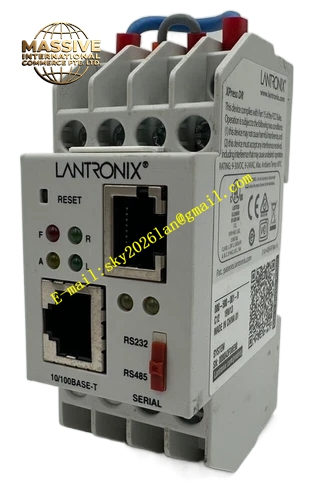
Description
LANTRONIX 080‑580‑001‑R, B12, 16W47
Technical Specifications Power supply range: 9‑30 VDC, 9‑24 VAC Ethernet port: 10/100 Base‑T auto‑negotiation RJ45 Serial ports: Multi‑mode configurable RS‑232 / RS‑422 / RS‑485 Maximum serial baud rate: 921.6 kbps Hardware revision: B12 Production batch identifier: 16W47 Operating temperature: ‑40 °C to +65 °C Supported protocols: TCP, UDP, DHCP, HTTP, HTTPS, SNMP, Telnet, Modbus TCP
Functional Features Transparent serial tunneling for bidirectional data transmission. Built‑in web configuration interface accessible via standard web browser. Supports remote firmware downloading and upgrade. Comprehensive LED status indicators for power, network link, data transmit and receive activity. Supports static IP, DHCP and Auto‑IP address assignment modes. Password‑protected configuration access to prevent unauthorized modification. DIN‑rail mounting compatible.
Application Scenarios Industrial factory automation, remote monitoring of field instruments, power industry substation serial equipment networking, intelligent building control system serial device interconnection, logistics and warehouse automation equipment communication transformation, industrial MES data acquisition terminals.
Performance Parameters Auto‑MDI‑X Ethernet port function eliminating crossover cable requirement. Multiple concurrent TCP session support. Hardware transient voltage surge suppression on power and signal interfaces. Low power consumption for continuous cabinet operation.
Material Composition Industrial flame‑retardant ABS plastic outer casing, high‑temperature resistant FR‑4 multilayer circuit board, metal DIN‑rail mounting bracket, gold‑plated RJ45 and terminal block contacts.
Structural Features Compact vertical cabinet‑friendly form factor, integrated DIN‑rail mounting clip, front‑panel LED status indicators, screw‑type terminal blocks for power and serial signals, front‑mounted RJ45 Ethernet connector.
Working Principle The internal embedded processor captures serial data frames from connected field equipment, encapsulates payload into TCP/UDP Ethernet packets for transmission over local area network. Inbound Ethernet packets are de‑encapsulated and converted back to standard serial electrical signals for target serial devices. All protocol conversion executes locally on‑board without external computing hardware dependency.
Installation Requirements Secure unit on standard DIN‑EN 50022 mounting rail inside closed control cabinet. Reserve surrounding clearance for natural convection cooling. Wire power terminals strictly following polarity marking. Route serial communication cables away from high‑power motor and variable‑frequency drive power cables. Connect protective earth ground to chassis ground terminal.
Usage Notes Do not apply voltage exceeding 30 VDC to power input terminals. Always back up configuration file before firmware upgrade operations. Document unit MAC address for network asset management. Avoid installation in environments with heavy dust, moisture or corrosive gas exposure. Tighten terminal block screws to specified torque to resist vibration‑induced loose connections.