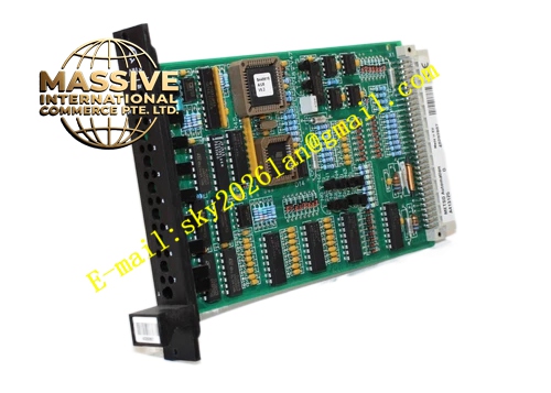
Description
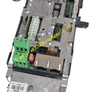
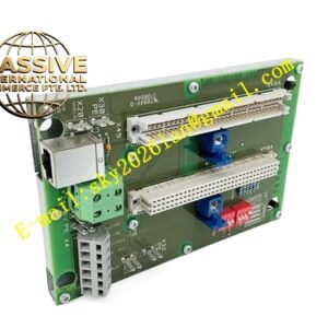
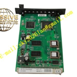
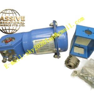
METSO A413146
Technical Specifications
- Communication protocol: Foundation Fieldbus H1, IEC 61158-2
- Power supply: Bus powered, 9V DC to 32V DC
- Current consumption: 15mA to 18mA typical
- Operating temperature: -40°C to +85°C
- Storage temperature: -40°C to +90°C
- Relative humidity: 5% to 95%, non-condensing
- Mounting: Internal installation inside ND9000 intelligent valve positioner
- Diagnostic functions: Valve friction monitoring, actuator speed diagnosis, supply pressure monitoring, travel deviation fault, electronic circuit self-test
Functional Features
- Foundation Fieldbus H1 digital communication to receive setpoint and upload valve diagnostic data.
- Embedded PID control algorithm for closed loop valve positioning regulation.
- Process travel feedback signal from A413111 potentiometer assembly and calculate valve opening.
- Drive pneumatic relay to adjust air volume to valve actuator for precise stroke control.
- Execute advanced valve diagnostics including friction curve, stroke speed, supply pressure and seat leakage estimation.
- Integrate standard Fieldbus function blocks including analog output, PID, resource and transducer blocks.
- Store valve calibration parameters, fault history and diagnostic logs in onboard non-volatile memory.
- Continuous power-up self-test and runtime hardware self-check.
Application Scenarios Digital fieldbus control valve in pulp and paper plant, chemical plant Foundation Fieldbus control loop, refinery smart valve asset management, water treatment digital valve control, power plant smart valve monitoring.
Performance Parameters
- Control loop response time: Less than 100ms
- Positioning accuracy: ±0.25% full valve stroke
- ITK interoperability compliance: Foundation Fieldbus ITK standard
- Non-volatile memory retention: 10 years data retention without power supply
- Diagnostic sampling rate: 100Hz for valve dynamic data
Material Composition
- Main PCB: FR-4 multi-layer flame retardant printed circuit board with conformal coating
- Main microcontroller: Industrial grade low power microprocessor
- Fieldbus communication transceiver: Foundation Fieldbus dedicated chip
- Non-volatile memory: Industrial flash memory chip
- Analog signal conditioning chip: Precision operational amplifier
- Internal connectors: Gold plated pin header connectors
Structural Characteristics Compact rectangular PCB assembly designed to fit inside ND9000 positioner housing. Multiple gold plated internal connectors connect to potentiometer feedback board, pneumatic relay, HMI display board and fieldbus terminal block. PCB layout separates low speed analog feedback circuit and digital communication circuit to reduce electromagnetic interference. The whole PCB is coated with three-proof conformal coating for vibration and moisture resistance.
Working Principle A413146 receives digital setpoint command from Foundation Fieldbus network. The board reads actual valve travel signal from A413111 potentiometer assembly. Internal PID algorithm compares setpoint and actual travel and calculates required pneumatic output. It sends drive signal to pneumatic relay to adjust air supply to valve actuator. The board continuously records valve movement data and calculates friction and speed characteristics. Diagnostic data and valve health status are transmitted back to DCS host system through Foundation Fieldbus.
Installation Requirements
- Open ND9000 positioner electronic compartment cover and install A413146 on internal mounting posts.
- Plug in all internal harness connectors including travel feedback, pneumatic drive and HMI display.
- Connect Foundation Fieldbus bus cable to positioner terminal block.
- Execute positioner auto-calibration and Fieldbus device address assignment after assembly.
- Verify communication connection with DCS Fieldbus card.
- Reinstall positioner electronic cover and sealing gasket to maintain enclosure protection rating.
Usage Precautions
- Use anti-static wristband during installation. Static electricity damages sensitive electronic components.
- Confirm bus voltage stays within 9V DC to 32V DC operating range.
- Do not short circuit fieldbus terminals during wiring.
- All calibration parameters must be saved after commissioning.
- Do not clean PCB surface with liquid solvent.
- Replace whole board when communication failure or control circuit fault occurs. No on-site component repair.