Description
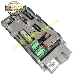
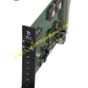
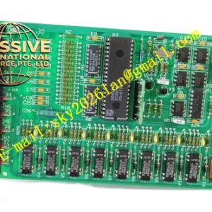
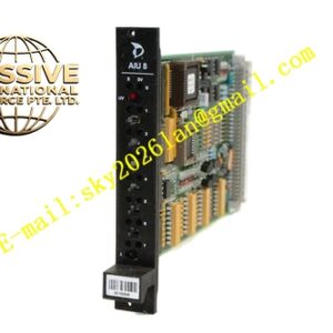
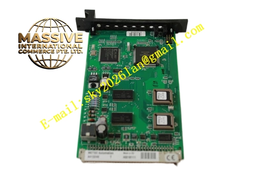
METSO A413659
Technical Specifications: 6-channel pulse input; support dry contact and 24VDC pulse signal; maximum input frequency 10kHz; backplane 24VDC power supply; rack plug-in installation; operating temperature range 0℃ to +55℃; each channel LED status indicator; protection class IP20.
Functional Features: High-speed pulse signal acquisition and counting; frequency measurement function; hardware pulse filtering; single-channel fault isolation; module self-diagnosis; upload counting data and fault alarm to DCS host system.
Application Scenarios: Flow cumulative measurement cabinet in thermal power plant; flow meter pulse collection cabinet in chemical plant; encoder position signal cabinet in pulp and paper production line; rotating equipment speed monitoring cabinet in water treatment plant.
Performance Parameters: High pulse counting accuracy; no signal distortion during long-distance transmission; strong anti-electromagnetic interference capability; support 7×24 hours uninterrupted continuous operation.
Material Composition: Glass fiber epoxy multilayer PCB circuit board; high-speed counting chip; photoelectric isolation components; gold-plated edge connector; metal front panel; circuit board coated with three-proof protective coating.
Structural Features: Rack plug-in modular structure; front panel equipped with LED indicators for power, running and channel fault status; rear gold-plated edge connector connects to DCS rack backplane bus; pulse input circuit and logic circuit are physically separated; panel fitted with mechanical locking buckle.
Working Principle: Pulse signal from field flow meter or speed sensor is transmitted to A413659 module through terminal base. Internal high-speed chip captures pulse edge and completes counting and frequency calculation. Calculated data is uploaded to DCS controller through backplane bus. The module monitors channel signal abnormality and uploads alarm message.
Installation Requirements: Install in designated slot of Metso DNA I/O rack and match with original terminal base. Use twisted shielded cable for pulse signal. Shield layer adopts single-point grounding. Pulse cables must be kept away from frequency converter and high-power motor cables. Cabinet protective grounding terminal must be connected reliably.
Precautions for Use: Confirm pulse signal voltage level before wiring. Cut off sensor power before wiring work. Do not access high voltage signal to pulse channel. Cut off rack backplane power before module disassembly. Check shielding cable grounding status regularly. Avoid dust accumulation on module.