Description
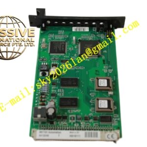
Metso AI3281
Technical Specifications Multiple galvanically isolated analog input channels; supports 4-20mA current input; 16-bit analog-to-digital conversion resolution; basic measurement accuracy ±0.15% full scale; isolation withstand voltage 1500V AC; 24V DC power supply; operating temperature -20°C to +70°C; IP20 protection class.
Functional Features Receives analog measurement signals from pressure, flow, level and temperature transmitters. Converts raw analog signals into digital engineering values configurable by channel. Detects open circuit and short circuit faults on field loops and reports alarms to the controller. Transmits real-time measurement data and diagnostic information through the rack backplane bus. Supports overvoltage surge protection for field wiring.
Application Scenarios Pulp and paper continuous production lines, mineral processing plants, cement production control systems, industrial wastewater treatment processes, heavy industry material conveying monitoring.
Performance Parameters High channel density with low inter-channel crosstalk; strong noise suppression in high electromagnetic interference environments; stable long-term measurement without frequent recalibration; fast fault reporting speed.
Material Composition Main printed circuit board uses FR-4 flame-retardant multilayer substrate; ADC and signal processing chips are industrial wide-temperature semiconductors; optocoupler devices provide galvanic isolation; backplane gold fingers use gold-plated copper contacts; outer shell is flame-retardant engineering plastic; terminal screws and contact pieces are nickel-plated copper alloy.
Structural Characteristics Rack plug-in module form factor compatible with Metso standard control racks. Front panel is equipped with power, communication and fault status LED indicators. Rear gold finger connector connects to rack backplane for power and bus communication. Field instrument wiring connects to front terminal blocks. Mechanical locking clip prevents loosening under continuous vibration.
Working Principle Field analog signals flow into each channel’s conditioning and isolation circuit. The analog-to-digital converter converts analog quantities into digital values. The onboard processor converts raw digital data into readable engineering values according to scaling settings. All measurement data and fault status upload to the main controller via the backplane bus.
Installation Requirements Power down the control rack before installing or replacing the module. Insert the module into the designated rack slot and fasten the locking clip. Wire field transmitters with shielded twisted-pair cables to module terminals. Configure channel parameters and alarm limits in supporting engineering software. Carry out loop signal testing after commissioning.
Precautions for Use Maintain single-point grounding for cable shielding. Avoid installing the module adjacent to large frequency converters. Do not overload input channels with excessive voltage. Back up control configuration before module replacement.