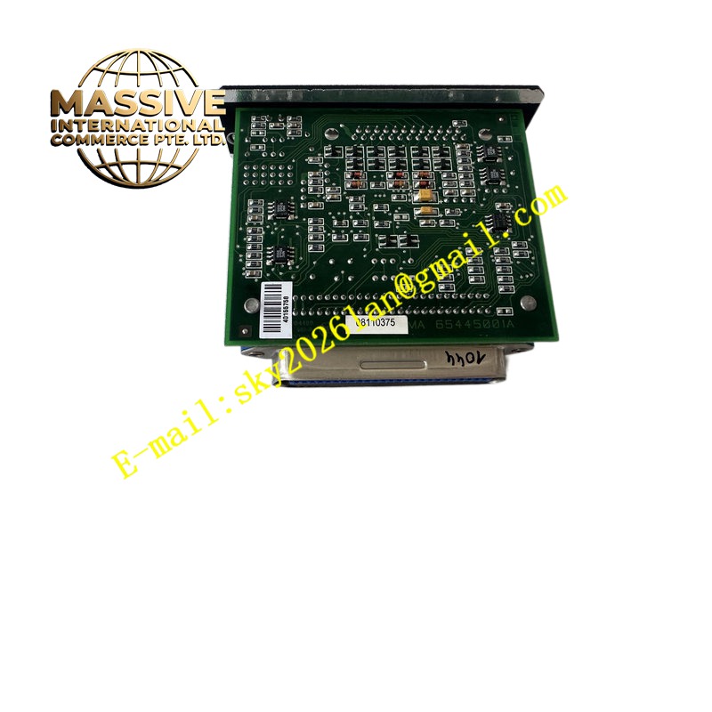
Description
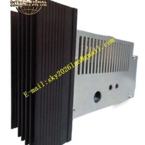
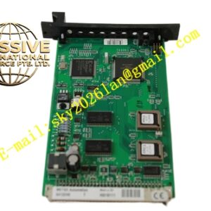
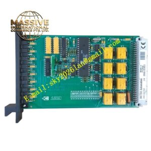
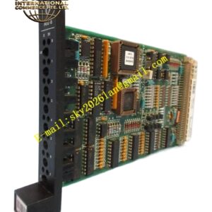
Metso D201190L
Technical Specifications
Brand: Metso
Product Model: D201190L
Product Type: Analog Output Module
Dimensions: 263 mm × 58 mm × 28 mm
Mounting Type: DIN rail or rack-mounted
Output Signal Types: 4-20 mA, 0-10 V, 0-5 V (configurable)
Number of Output Channels: Typically 4 or 8 channels per module
Output Resolution: 16-bit or higher
Output Accuracy: ±0.1% of full scale
Load Impedance: 0 to 500 ohms for current outputs, greater than 2 kiloohms for voltage outputs
Response Time: Less than 100 ms per channel
Operating Temperature: 0°C to 60°C (32°F to 140°F)
Storage Temperature: -20°C to 70°C (-4°F to 158°F)
Relative Humidity: 5% to 95% (non-condensing)
Supply Voltage: 24 V DC
Power Consumption: Typically 3-5 W
Isolation Voltage: 500 V AC between channels and ground
Certification Standards: CE, UL, CSA compliant
Functional Features
High-Precision Signal Output: 16-bit resolution ensures accurate generation of control signals for precise actuator positioning
Multi-Channel Configuration: Multiple output channels per module reduce the number of modules required and save cabinet space
Configurable Output Types: Supports both current loop (4-20 mA) and voltage (0-10 V) signals for flexible actuator integration
Electrical Isolation: Channel-to-ground isolation protects the control system from ground loops and electrical noise
Diagnostics and Status Indication: Built-in self-diagnostics with LED indicators for power, communication, and fault conditions
Hot-Swap Capability: Supports module replacement without shutting down the entire control system
Output Hold on Fault: Maintains the last valid output value or a predefined safe value in case of communication loss or controller failure
Noise Filtering: Integrated output filtering reduces the impact of electrical interference on connected field devices
Application Scenarios
Mineral Processing: Control of slurry valve positions, pump speed references, and reagent dosing rates in grinding and flotation circuits
Pulp and Paper Industry: Control valve positioning for stock flow, chemical addition, and steam pressure regulation
Power Generation: Control of feedwater valves, fuel flow valves, and damper positions in boiler systems
Water and Wastewater Treatment: Control of chemical dosing pumps, valve actuators, and blower speeds
Chemical Processing: Control of reactor feed valves, temperature control valves, and pressure regulating valves
Oil and Gas: Control of pipeline valves, compressor speed references, and separator level control valves
HVAC Systems: Control of damper actuators, valve positions, and fan speed references in building management systems
Performance Parameters
Output Resolution: 16-bit
Accuracy: ±0.1% of full scale
Channel Response Time: Less than 100 ms
Load Regulation: Less than 0.01% change for full load variation
Temperature Drift: Less than 50 ppm per degree Celsius
Settling Time: Less than 50 ms to within 0.1% of final value after step command change
Update Rate: 10 updates per second per channel
Short Circuit Protection: Current outputs protected against continuous short circuit
Material Composition
Industrial-grade fiberglass-reinforced printed circuit board with surface-mounted electronic components, precision digital-to-analog converter chips, high-quality isolation transformers and optocouplers for channel isolation, precision operational amplifiers and current drivers for signal output, aluminum or reinforced polymer housing for structural integrity and heat dissipation, gold-plated connector pins for reliable signal transmission, flame-retardant materials compliant with UL94 V-0 standards
Structural Features
Compact modular form factor (263 mm × 58 mm × 28 mm) designed for DIN rail or rack mounting, front-panel LED indicators for power status, channel activity, and fault conditions, removable terminal block connectors for easy wiring and maintenance, clearly labeled channel designations and terminal markings, integrated mounting clips for secure installation, ventilation slots for passive cooling, robust enclosure suitable for industrial control cabinet environments, keyed connectors to prevent incorrect module insertion
Working Principle
The D201190L receives digital output commands from the main controller via the module’s backplane interface. The controller sends the desired output value for each channel as a digital word. The module’s onboard microcontroller processes these commands and generates the corresponding analog signal using a high-resolution digital-to-analog converter. The DAC output is then conditioned by an output amplifier circuit that provides the necessary current drive capability for current loop outputs (4-20 mA) or voltage buffering for voltage outputs (0-10 V). Each output channel is electrically isolated from the backplane and other channels to prevent ground loops and protect against voltage transients. The module continuously monitors its own health and the status of each output channel. In the event of a communication failure or controller fault, the module can be configured to hold the last valid output value or switch to a predefined safe value (such as 4 mA or 0 V) to ensure process safety. Diagnostic information including open circuit detection, short circuit detection, and overtemperature conditions is reported to the controller through diagnostic registers.
Installation Requirements
Verify the module is undamaged and all accessories are complete before installation
Mount the module securely on a DIN rail or in a compatible rack using the provided mounting hardware
Ensure adequate ventilation around the module to maintain operating temperature within 0°C to 60°C
Connect field wiring to the terminal block using properly sized shielded cables to minimize noise pickup
Observe correct polarity when connecting current loop and voltage outputs
Use separate cable trays for analog signal cables and power cables to reduce electromagnetic interference
Ensure proper grounding of the module and all connected field instruments
Configure output channel types (current or voltage) and fault behavior using the system configuration software before commissioning
Verify that the supply voltage is within the specified range (24 V DC) before powering the module
Verify that the connected field devices are compatible with the module’s output signal types and load impedance specifications
Usage Precautions
Do not exceed the maximum load impedance specified for each output channel to ensure proper signal delivery
Ensure that all field wiring is properly shielded and grounded to minimize electrical noise interference
Do not disconnect or connect field wiring while the system is powered unless specifically designed for hot-swap operation
Regularly check the module’s LED indicators for any fault conditions and address them promptly
Back up the module configuration settings before making changes to the system
Keep the module clean and free of dust accumulation that could impair heat dissipation
Verify that the output signal types match the requirements of the connected field devices before commissioning
Configure appropriate fault behavior (hold last value or safe value) for each channel based on process safety requirements
Handle the module with care during installation to avoid electrostatic discharge damage to sensitive electronic components
Refer to the official Metso documentation for detailed troubleshooting procedures and error code definitions